Lenovo J105 Hardware Maintenance Manual - Page 102
replacement.
 |
View all Lenovo J105 manuals
Add to My Manuals
Save this manual to your list of manuals |
Page 102 highlights
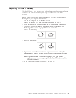
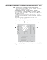
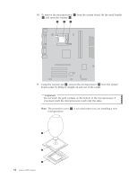
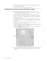
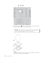
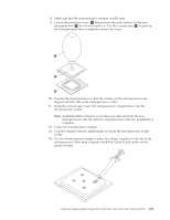
20. Connect all the cables to the system board. See "Identifying parts on the system board" on page 85 21. Go to "Completing the FRU replacement." on page 111. Replacing the system board (Types 8257, 8258, and 8259) Note: When replacing the system board, a new retention bracket for the microprocessor heat sink is required. Make sure you have a new retention bracket before beginning this procedure. 1. Remove only the left-side cover. See "Removing the covers" on page 82. 2. Lay the computer on the right side to make the system board accessible. 3. Remove any adapter cards installed in the PCI connectors. See "Replacing a PCI adapter" on page 90. 4. Carefully take note of the location of all cable connections on the system board and disconnect all cables. See "Identifying parts on the system board" on page 85. 5. Remove the screws that secure the system board to the chassis. 6. Lift the system board out of the chassis. 7. Remove the memory modules from the failing system board and install them in the same location on the new system board. 8. Rotate handle 1 to release the heat sink clamp and then disengage the clamp from the plastic retention bracket. 9. Lift the heat sink and fan assembly off the failing system board. Lay the heat sink on its side so that the thermal grease does not come in contact with anything. 96 Lenovo 3000 J Series
-
 1
1 -
2
-
3
-
4
-
5
-
6
-
7
-
8
-
9
-
10
-
11
-
12
-
13
-
14
-
15
-
16
-
17
-
18
-
19
-
20
-
21
-
22
-
23
-
24
-
25
-
26
-
27
-
28
-
29
-
30
-
31
-
32
-
33
-
34
-
35
-
36
-
37
-
38
-
39
-
40
-
41
-
42
-
43
-
44
-
45
-
46
-
47
-
48
-
49
-
50
-
51
-
52
-
53
-
54
-
55
-
56
-
57
-
58
-
59
-
60
-
61
-
62
-
63
-
64
-
65
-
66
-
67
-
68
-
69
-
70
-
71
-
72
-
73
-
74
-
75
-
76
-
77
-
78
-
79
-
80
-
81
-
82
-
83
-
84
-
85
-
86
-
87
-
88
-
89
-
90
-
91
-
92
-
93
-
94
-
95
-
96
-
 97
97 -
 98
98 -
 99
99 -
 100
100 -
 101
101 -
 102
102 -
 103
103 -
 104
104 -
 105
105 -
 106
106 -
 107
107 -
108
-
109
-
110
-
111
-
112
-
113
-
114
-
115
-
116
-
117
-
118
-
119
-
120
-
121
-
122
-
123
-
124
-
125
-
126
-
127
-
128
-
129
-
130
-
131
-
132
-
133
-
134
-
135
-
136
-
137
-
138
-
139
-
140
-
141
-
142
-
143
-
144
-
145
-
146
-
147
-
148
-
149
-
150
-
151
-
152
-
153
-
154
-
155
-
156
-
157
-
158
-
159
-
160
-
161
-
162
-
163
-
164
-
165
-
166
-
167
-
168
-
169
-
170
-
171
-
172
-
173
-
174
-
175
-
176
-
177
-
178
-
179
-
180
-
181
-
182
-
183
-
184
-
185
-
186
-
187
-
188
-
189
-
190
-
191
-
192
-
193
-
194
-
195
-
196
-
197
-
198
-
199
-
200
-
201
-
202
-
203
-
204
-
205
-
206
-
207
-
208
-
209
-
210
-
211
-
212
-
213
-
214
-
215
-
216
-
217
-
218
 |
 |
