Lenovo J105 Hardware Maintenance Manual - Page 134
screw
 |
View all Lenovo J105 manuals
Add to My Manuals
Save this manual to your list of manuals |
Page 134 highlights
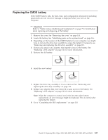
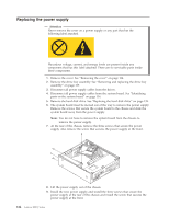
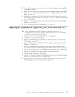
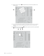
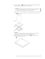
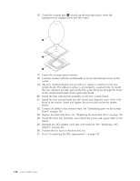
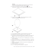
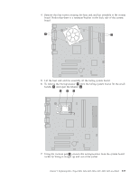
16. Using the vacuum pen 1 to pick up the microprocessor, lower the microprocessor straight down into the socket. 17. Lower the microprocessor retainer. 18. Lock the retainer with the small handle to secure the microprocessor in the socket. 19. The new retention bracket has an adhesive surface to attach it to the new system board. The adhesive surface is protected by a peel-off film. To install the new retention bracket, peel off the film, push the posts through the holes in the system board until secure against the board. 20. Install the heat sink and fan assembly on the new system board. 21. Install the new system board into the chassis and align the screw holes with those in the chassis. Insert and tighten the screws that secure the system board. 22. Connect all cables to the system board. See "Identifying parts on the system board" on page 116 23. Replace the hard disk drive. See "Replacing the hard disk drive" on page 139. 24. Install the drive bay assembly and connect the power and signal cables to the drives. 25. Reinstall any PCI adapter cards that were removed. See "Replacing a PCI adapter" on page 121. 26. Position the fan duct on the heat sink fan. 27. Go to "Completing the FRU replacement." on page 143. 128 Lenovo 3000 J Series
-
 1
1 -
2
-
3
-
4
-
5
-
6
-
7
-
8
-
9
-
10
-
11
-
12
-
13
-
14
-
15
-
16
-
17
-
18
-
19
-
20
-
21
-
22
-
23
-
24
-
25
-
26
-
27
-
28
-
29
-
30
-
31
-
32
-
33
-
34
-
35
-
36
-
37
-
38
-
39
-
40
-
41
-
42
-
43
-
44
-
45
-
46
-
47
-
48
-
49
-
50
-
51
-
52
-
53
-
54
-
55
-
56
-
57
-
58
-
59
-
60
-
61
-
62
-
63
-
64
-
65
-
66
-
67
-
68
-
69
-
70
-
71
-
72
-
73
-
74
-
75
-
76
-
77
-
78
-
79
-
80
-
81
-
82
-
83
-
84
-
85
-
86
-
87
-
88
-
89
-
90
-
91
-
92
-
93
-
94
-
95
-
96
-
97
-
98
-
99
-
100
-
101
-
102
-
103
-
104
-
105
-
106
-
107
-
108
-
109
-
110
-
111
-
112
-
113
-
114
-
115
-
116
-
117
-
118
-
119
-
120
-
121
-
122
-
123
-
124
-
125
-
126
-
127
-
128
-
 129
129 -
 130
130 -
 131
131 -
 132
132 -
 133
133 -
 134
134 -
 135
135 -
 136
136 -
 137
137 -
 138
138 -
 139
139 -
140
-
141
-
142
-
143
-
144
-
145
-
146
-
147
-
148
-
149
-
150
-
151
-
152
-
153
-
154
-
155
-
156
-
157
-
158
-
159
-
160
-
161
-
162
-
163
-
164
-
165
-
166
-
167
-
168
-
169
-
170
-
171
-
172
-
173
-
174
-
175
-
176
-
177
-
178
-
179
-
180
-
181
-
182
-
183
-
184
-
185
-
186
-
187
-
188
-
189
-
190
-
191
-
192
-
193
-
194
-
195
-
196
-
197
-
198
-
199
-
200
-
201
-
202
-
203
-
204
-
205
-
206
-
207
-
208
-
209
-
210
-
211
-
212
-
213
-
214
-
215
-
216
-
217
-
218
 |
 |
