Lenovo J105 Hardware Maintenance Manual - Page 94
Removing, replacing, front, bezel, Replacing, memory, module
 |
View all Lenovo J105 manuals
Add to My Manuals
Save this manual to your list of manuals |
Page 94 highlights
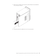
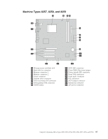
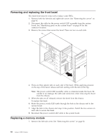
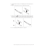
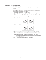
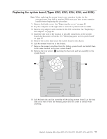
Removing and replacing the front bezel The front bezel must be removed to replace some FRUs. 1. Remove both the left-side and right-side covers. See "Removing the covers" on page 82. 2. Disconnect the cable for the power switch/LED assembly from the system board. See "Identifying parts on the system board" on page 85 for the connector location. 3. Remove the screws that secure the bezel. There are two on each side. 4. There are three plastic tabs on each side of the bezel. While applying pressure on the top of the bezel, release each tab starting with the tabs at the top. Note: The power switch/LED assembly cable is connected inside the bezel. Be careful to not damage the cable and connectors when removing the bezel from the chassis. 5. When the tabs are all released, remove the bezel from the chassis. To replace the bezel: 6. Route the power switch/LED cable through the hole in the chassis and to the system board. 7. Align the tabs in the chassis and snap it into position. Install the two screws on each side to secure the bezel. 8. Reconnect the power switch/LED cable to the system board. Replacing a memory module 1. Remove the left-side cover. See "Removing the covers" on page 82. 88 Lenovo 3000 J Series
-
 1
1 -
2
-
3
-
4
-
5
-
6
-
7
-
8
-
9
-
10
-
11
-
12
-
13
-
14
-
15
-
16
-
17
-
18
-
19
-
20
-
21
-
22
-
23
-
24
-
25
-
26
-
27
-
28
-
29
-
30
-
31
-
32
-
33
-
34
-
35
-
36
-
37
-
38
-
39
-
40
-
41
-
42
-
43
-
44
-
45
-
46
-
47
-
48
-
49
-
50
-
51
-
52
-
53
-
54
-
55
-
56
-
57
-
58
-
59
-
60
-
61
-
62
-
63
-
64
-
65
-
66
-
67
-
68
-
69
-
70
-
71
-
72
-
73
-
74
-
75
-
76
-
77
-
78
-
79
-
80
-
81
-
82
-
83
-
84
-
85
-
86
-
87
-
88
-
 89
89 -
 90
90 -
 91
91 -
 92
92 -
 93
93 -
 94
94 -
 95
95 -
 96
96 -
 97
97 -
 98
98 -
 99
99 -
100
-
101
-
102
-
103
-
104
-
105
-
106
-
107
-
108
-
109
-
110
-
111
-
112
-
113
-
114
-
115
-
116
-
117
-
118
-
119
-
120
-
121
-
122
-
123
-
124
-
125
-
126
-
127
-
128
-
129
-
130
-
131
-
132
-
133
-
134
-
135
-
136
-
137
-
138
-
139
-
140
-
141
-
142
-
143
-
144
-
145
-
146
-
147
-
148
-
149
-
150
-
151
-
152
-
153
-
154
-
155
-
156
-
157
-
158
-
159
-
160
-
161
-
162
-
163
-
164
-
165
-
166
-
167
-
168
-
169
-
170
-
171
-
172
-
173
-
174
-
175
-
176
-
177
-
178
-
179
-
180
-
181
-
182
-
183
-
184
-
185
-
186
-
187
-
188
-
189
-
190
-
191
-
192
-
193
-
194
-
195
-
196
-
197
-
198
-
199
-
200
-
201
-
202
-
203
-
204
-
205
-
206
-
207
-
208
-
209
-
210
-
211
-
212
-
213
-
214
-
215
-
216
-
217
-
218
 |
 |
