Lenovo J105 Hardware Maintenance Manual - Page 5
Contents - specifications
 |
View all Lenovo J105 manuals
Add to My Manuals
Save this manual to your list of manuals |
Page 5 highlights
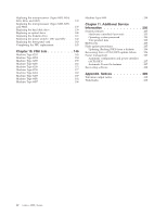
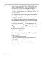
Contents Chapter 1. About this manual . . . . . 1 Important Safety Information 1 Important information about replacing RoHS compliant FRUs 2 Chapter 2. Safety information . . . . . 3 General safety 3 Electrical safety 3 Safety inspection guide 5 Handling electrostatic discharge-sensitive devices . . 6 Grounding requirements 6 Safety notices (multi-lingual translations) . . . . . 7 Chapter 3. General information . . . . 37 The Lenovo Care program 37 Additional information resources 37 Specifications 38 Machine types 8252, 8253, 8254, 8255, 8256, 8257, 8258, and 8259 38 Machine types 8453, 8454, 8455, 8456, 8457, 8458, 8459, and 8460 39 Chapter 4. General Checkout . . . . . 41 Problem determination tips 41 Chapter 5. Diagnostics using PC-Doctor for DOS 43 Starting PC-Doctor from a diagnostic diskette or CD-ROM 43 Diagnostics program download 43 Navigating through the diagnostics programs . . . 44 Running diagnostics tests 44 Test selection 44 Test results 44 Fixed disk advanced test (FDAT 45 Quick and Full erase - hard drive 46 Viewing the test log 48 Chapter 6. Using the Setup Utility . . . 49 Starting the Setup Utility program 49 Viewing and changing settings 49 Using passwords 49 User Password 49 Administrator or Supervisor Password . . . . 50 Selecting a startup device 51 Selecting a temporary startup device . . . . . 51 Changing the startup device sequence . . . . 51 Exiting from the Setup Utility program . . . . . 51 Chapter 7. Symptom-to-FRU Index . . . 53 Hard disk drive boot error 53 Power Supply Problems 53 Diagnostic error codes 54 Beep symptoms 75 © Lenovo 2006. Portions © IBM Corp. 2005, 2006. POST error codes 76 Miscellaneous error messages 78 Undetermined problems 79 Chapter 8. Replacing FRUs (Types 8252, 8253, 8254, 8255, 8256, 8257, 8258, and 8259 81 Rear connectors 82 Removing the covers 82 Locations 84 Identifying parts on the system board . . . . . 85 Machine Types 8252, 8253, and 8254 . . . . . 85 Machine Types 8255 and 8256 86 Machine Types 8257, 8258, and 8259 . . . . . 87 Removing and replacing the front bezel . . . . . 88 Replacing a memory module 88 Replacing a PCI adapter 90 Replacing the CMOS battery 91 Replacing the power supply 92 Replacing the system board (Types 8252, 8253, 8254, 8255, and 8256 93 Replacing the system board (Types 8257, 8258, and 8259 96 Replacing the microprocessor (Types 8252, 8253, 8254, 8255, and 8256 99 Replacing the microprocessor (Types 8257, 8258, and 8259 103 Replacing the primary hard disk drive . . . . . 107 Replacing an optical drive 108 Replacing the diskette drive 109 Replacing the power switch/ LED assembly . . . 110 Replacing the front panel card assembly . . . . 111 Completing the FRU replacement 111 Chapter 9. Replacing FRUs (Types 8453, 8454, 8455, 8456, 8457, 8458, 8459, and 8460 113 Rear connectors 114 Removing the cover 114 Locations 115 Identifying parts on the system board . . . . . 116 Machine Types 8453, 8454, and 8455 . . . . . 116 Machine Types 8456 and 8457 117 Machine Types 8458, 8459, and 8460 . . . . . 118 Removing and replacing the drive bay assembly 119 Replacing a memory module 120 Replacing a PCI adapter 121 Replacing the CMOS battery 123 Replacing the power supply 124 Replacing the system board (Types 8453, 8454, 8455, 8456, and 8457 125 Replacing the system board (Types 8458, 8459, and 8460 129 iii
-
 1
1 -
 2
2 -
 3
3 -
 4
4 -
 5
5 -
 6
6 -
 7
7 -
 8
8 -
 9
9 -
 10
10 -
 11
11 -
12
-
13
-
14
-
15
-
16
-
17
-
18
-
19
-
20
-
21
-
22
-
23
-
24
-
25
-
26
-
27
-
28
-
29
-
30
-
31
-
32
-
33
-
34
-
35
-
36
-
37
-
38
-
39
-
40
-
41
-
42
-
43
-
44
-
45
-
46
-
47
-
48
-
49
-
50
-
51
-
52
-
53
-
54
-
55
-
56
-
57
-
58
-
59
-
60
-
61
-
62
-
63
-
64
-
65
-
66
-
67
-
68
-
69
-
70
-
71
-
72
-
73
-
74
-
75
-
76
-
77
-
78
-
79
-
80
-
81
-
82
-
83
-
84
-
85
-
86
-
87
-
88
-
89
-
90
-
91
-
92
-
93
-
94
-
95
-
96
-
97
-
98
-
99
-
100
-
101
-
102
-
103
-
104
-
105
-
106
-
107
-
108
-
109
-
110
-
111
-
112
-
113
-
114
-
115
-
116
-
117
-
118
-
119
-
120
-
121
-
122
-
123
-
124
-
125
-
126
-
127
-
128
-
129
-
130
-
131
-
132
-
133
-
134
-
135
-
136
-
137
-
138
-
139
-
140
-
141
-
142
-
143
-
144
-
145
-
146
-
147
-
148
-
149
-
150
-
151
-
152
-
153
-
154
-
155
-
156
-
157
-
158
-
159
-
160
-
161
-
162
-
163
-
164
-
165
-
166
-
167
-
168
-
169
-
170
-
171
-
172
-
173
-
174
-
175
-
176
-
177
-
178
-
179
-
180
-
181
-
182
-
183
-
184
-
185
-
186
-
187
-
188
-
189
-
190
-
191
-
192
-
193
-
194
-
195
-
196
-
197
-
198
-
199
-
200
-
201
-
202
-
203
-
204
-
205
-
206
-
207
-
208
-
209
-
210
-
211
-
212
-
213
-
214
-
215
-
216
-
217
-
218
 |
 |
