Lenovo J105 Hardware Maintenance Manual - Page 116
Replacing, power, switch, assembly
 |
View all Lenovo J105 manuals
Add to My Manuals
Save this manual to your list of manuals |
Page 116 highlights
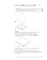
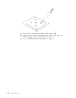
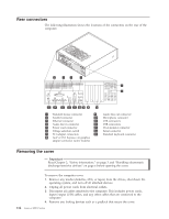
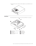
Replacing the power switch/ LED assembly 1. Remove the front bezel. See "Removing and replacing the front bezel" on page 88. 2. Disconnect the power switch/LED assembly cable from the system board. See "Identifying parts on the system board" on page 85. 3. Remove the power switch/LED assembly by disconnecting it from the inside of the bezel. 4. Install the new power switch/LED assembly into the bezel. 5. Route the cable for the new power switch/LED assembly through the hole in the chassis and to the system board. 6. Reinstall the bezel. See "Removing and replacing the front bezel" on page 88. 7. Reconnect the power switch/LED cable to the system board. 8. Go to "Completing the FRU replacement." on page 111. 110 Lenovo 3000 J Series
-
 1
1 -
2
-
3
-
4
-
5
-
6
-
7
-
8
-
9
-
10
-
11
-
12
-
13
-
14
-
15
-
16
-
17
-
18
-
19
-
20
-
21
-
22
-
23
-
24
-
25
-
26
-
27
-
28
-
29
-
30
-
31
-
32
-
33
-
34
-
35
-
36
-
37
-
38
-
39
-
40
-
41
-
42
-
43
-
44
-
45
-
46
-
47
-
48
-
49
-
50
-
51
-
52
-
53
-
54
-
55
-
56
-
57
-
58
-
59
-
60
-
61
-
62
-
63
-
64
-
65
-
66
-
67
-
68
-
69
-
70
-
71
-
72
-
73
-
74
-
75
-
76
-
77
-
78
-
79
-
80
-
81
-
82
-
83
-
84
-
85
-
86
-
87
-
88
-
89
-
90
-
91
-
92
-
93
-
94
-
95
-
96
-
97
-
98
-
99
-
100
-
101
-
102
-
103
-
104
-
105
-
106
-
107
-
108
-
109
-
110
-
 111
111 -
 112
112 -
 113
113 -
 114
114 -
 115
115 -
 116
116 -
 117
117 -
 118
118 -
 119
119 -
 120
120 -
 121
121 -
122
-
123
-
124
-
125
-
126
-
127
-
128
-
129
-
130
-
131
-
132
-
133
-
134
-
135
-
136
-
137
-
138
-
139
-
140
-
141
-
142
-
143
-
144
-
145
-
146
-
147
-
148
-
149
-
150
-
151
-
152
-
153
-
154
-
155
-
156
-
157
-
158
-
159
-
160
-
161
-
162
-
163
-
164
-
165
-
166
-
167
-
168
-
169
-
170
-
171
-
172
-
173
-
174
-
175
-
176
-
177
-
178
-
179
-
180
-
181
-
182
-
183
-
184
-
185
-
186
-
187
-
188
-
189
-
190
-
191
-
192
-
193
-
194
-
195
-
196
-
197
-
198
-
199
-
200
-
201
-
202
-
203
-
204
-
205
-
206
-
207
-
208
-
209
-
210
-
211
-
212
-
213
-
214
-
215
-
216
-
217
-
218
 |
 |

Replacing
the
power
switch/
LED
assembly
1.
Remove
the
front
bezel.
See
“Removing
and
replacing
the
front
bezel”
on
page
88.
2.
Disconnect
the
power
switch/LED
assembly
cable
from
the
system
board.
See
“Identifying
parts
on
the
system
board”
on
page
85.
3.
Remove
the
power
switch/LED
assembly
by
disconnecting
it
from
the
inside
of
the
bezel.
4.
Install
the
new
power
switch/LED
assembly
into
the
bezel.
5.
Route
the
cable
for
the
new
power
switch/LED
assembly
through
the
hole
in
the
chassis
and
to
the
system
board.
6.
Reinstall
the
bezel.
See
“Removing
and
replacing
the
front
bezel”
on
page
88.
7.
Reconnect
the
power
switch/LED
cable
to
the
system
board.
8.
Go
to
“Completing
the
FRU
replacement.”
on
page
111.
110
Lenovo
3000
J
Series