Lenovo J105 Hardware Maintenance Manual - Page 127
static-protective
 |
View all Lenovo J105 manuals
Add to My Manuals
Save this manual to your list of manuals |
Page 127 highlights
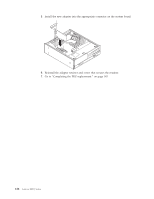
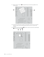
5. Make sure the notch 1 on the new memory module is aligned correctly with the connector key 2 on the socket. Insert the memory module straight down into the connector until it snaps into position and the retaining clips are closed. 6. Replace the drive bay assembly. See "Removing and replacing the drive bay assembly" on page 119. 7. Go to "Completing the FRU replacement." on page 143. Replacing a PCI adapter 1. Remove the computer cover. See "Removing the cover" on page 114. 2. Remove the screw that secures the adapter retainer and remove the retainer. 3. Remove the failing adapter. 4. Remove the new adapter from its static-protective package. Chapter 9. Replacing FRUs (Types 8453, 8454, 8455, 8456, 8457, 8458, 8459, and 8460) 121
-
 1
1 -
2
-
3
-
4
-
5
-
6
-
7
-
8
-
9
-
10
-
11
-
12
-
13
-
14
-
15
-
16
-
17
-
18
-
19
-
20
-
21
-
22
-
23
-
24
-
25
-
26
-
27
-
28
-
29
-
30
-
31
-
32
-
33
-
34
-
35
-
36
-
37
-
38
-
39
-
40
-
41
-
42
-
43
-
44
-
45
-
46
-
47
-
48
-
49
-
50
-
51
-
52
-
53
-
54
-
55
-
56
-
57
-
58
-
59
-
60
-
61
-
62
-
63
-
64
-
65
-
66
-
67
-
68
-
69
-
70
-
71
-
72
-
73
-
74
-
75
-
76
-
77
-
78
-
79
-
80
-
81
-
82
-
83
-
84
-
85
-
86
-
87
-
88
-
89
-
90
-
91
-
92
-
93
-
94
-
95
-
96
-
97
-
98
-
99
-
100
-
101
-
102
-
103
-
104
-
105
-
106
-
107
-
108
-
109
-
110
-
111
-
112
-
113
-
114
-
115
-
116
-
117
-
118
-
119
-
120
-
121
-
 122
122 -
 123
123 -
 124
124 -
 125
125 -
 126
126 -
 127
127 -
 128
128 -
 129
129 -
 130
130 -
 131
131 -
 132
132 -
133
-
134
-
135
-
136
-
137
-
138
-
139
-
140
-
141
-
142
-
143
-
144
-
145
-
146
-
147
-
148
-
149
-
150
-
151
-
152
-
153
-
154
-
155
-
156
-
157
-
158
-
159
-
160
-
161
-
162
-
163
-
164
-
165
-
166
-
167
-
168
-
169
-
170
-
171
-
172
-
173
-
174
-
175
-
176
-
177
-
178
-
179
-
180
-
181
-
182
-
183
-
184
-
185
-
186
-
187
-
188
-
189
-
190
-
191
-
192
-
193
-
194
-
195
-
196
-
197
-
198
-
199
-
200
-
201
-
202
-
203
-
204
-
205
-
206
-
207
-
208
-
209
-
210
-
211
-
212
-
213
-
214
-
215
-
216
-
217
-
218
 |
 |

5.
Make
sure
the
notch
±1²
on
the
new
memory
module
is
aligned
correctly
with
the
connector
key
±2²
on
the
socket.
Insert
the
memory
module
straight
down
into
the
connector
until
it
snaps
into
position
and
the
retaining
clips
are
closed.
6.
Replace
the
drive
bay
assembly.
See
“Removing
and
replacing
the
drive
bay
assembly”
on
page
119.
7.
Go
to
“Completing
the
FRU
replacement.”
on
page
143.
Replacing
a
PCI
adapter
1.
Remove
the
computer
cover.
See
“Removing
the
cover”
on
page
114.
2.
Remove
the
screw
that
secures
the
adapter
retainer
and
remove
the
retainer.
3.
Remove
the
failing
adapter.
4.
Remove
the
new
adapter
from
its
static-protective
package.
Chapter
9.
Replacing
FRUs
(Types
8453,
8454,
8455,
8456,
8457,
8458,
8459,
and
8460)
121