Lenovo J105 Hardware Maintenance Manual - Page 107
protective
 |
View all Lenovo J105 manuals
Add to My Manuals
Save this manual to your list of manuals |
Page 107 highlights
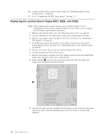
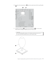
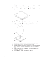
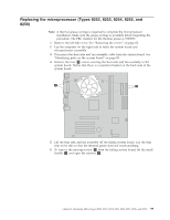
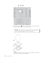
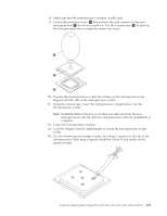
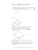
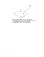
8. Make sure that the microprocessor retainer is fully open. 9. Loosen the protective cover 3 that protects the gold contacts on the new microprocessor 2 but do not remove it. Use the vacuum pen 1 to pick up the microprocessor then completely remove the cover. 10. Position the microprocessor so that the notches on the microprocessor are aligned with the tabs in the microprocessor socket. 11. Using the vacuum pen, lower the microprocessor straight down into the microprocessor socket. Note: Install the black protective cover that was removed from the new microprocessor onto the defective microprocessor after the installation is complete. 12. Lower the microprocessor retainer. 13. Lock the retainer with the small handle to secure the microprocessor in the socket. 14. Use the thermal grease syringe to place five drops of grease on the top of the microprocessor. Each drop of grease should be 0.03ml (3 tick marks on the grease syringe). Chapter 8. Replacing FRUs (Types 8252, 8253, 8254, 8255, 8256, 8257, 8258, and 8259) 101
-
 1
1 -
2
-
3
-
4
-
5
-
6
-
7
-
8
-
9
-
10
-
11
-
12
-
13
-
14
-
15
-
16
-
17
-
18
-
19
-
20
-
21
-
22
-
23
-
24
-
25
-
26
-
27
-
28
-
29
-
30
-
31
-
32
-
33
-
34
-
35
-
36
-
37
-
38
-
39
-
40
-
41
-
42
-
43
-
44
-
45
-
46
-
47
-
48
-
49
-
50
-
51
-
52
-
53
-
54
-
55
-
56
-
57
-
58
-
59
-
60
-
61
-
62
-
63
-
64
-
65
-
66
-
67
-
68
-
69
-
70
-
71
-
72
-
73
-
74
-
75
-
76
-
77
-
78
-
79
-
80
-
81
-
82
-
83
-
84
-
85
-
86
-
87
-
88
-
89
-
90
-
91
-
92
-
93
-
94
-
95
-
96
-
97
-
98
-
99
-
100
-
101
-
 102
102 -
 103
103 -
 104
104 -
 105
105 -
 106
106 -
 107
107 -
 108
108 -
 109
109 -
 110
110 -
 111
111 -
 112
112 -
113
-
114
-
115
-
116
-
117
-
118
-
119
-
120
-
121
-
122
-
123
-
124
-
125
-
126
-
127
-
128
-
129
-
130
-
131
-
132
-
133
-
134
-
135
-
136
-
137
-
138
-
139
-
140
-
141
-
142
-
143
-
144
-
145
-
146
-
147
-
148
-
149
-
150
-
151
-
152
-
153
-
154
-
155
-
156
-
157
-
158
-
159
-
160
-
161
-
162
-
163
-
164
-
165
-
166
-
167
-
168
-
169
-
170
-
171
-
172
-
173
-
174
-
175
-
176
-
177
-
178
-
179
-
180
-
181
-
182
-
183
-
184
-
185
-
186
-
187
-
188
-
189
-
190
-
191
-
192
-
193
-
194
-
195
-
196
-
197
-
198
-
199
-
200
-
201
-
202
-
203
-
204
-
205
-
206
-
207
-
208
-
209
-
210
-
211
-
212
-
213
-
214
-
215
-
216
-
217
-
218
 |
 |
