Lenovo J105 Hardware Maintenance Manual - Page 141
Lenovo J105 Manual
 |
View all Lenovo J105 manuals
Add to My Manuals
Save this manual to your list of manuals |
Page 141 highlights
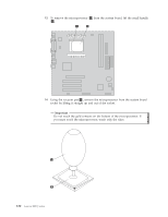
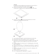
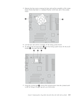
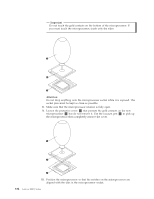
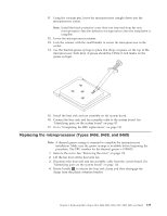
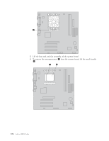
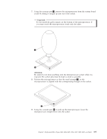
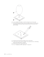
11. Using the vacuum pen, lower the microprocessor straight down into the microprocessor socket. Note: Install the black protective cover that was removed from the new microprocessor onto the defective microprocessor after the installation is complete. 12. Lower the microprocessor retainer. 13. Lock the retainer with the small handle to secure the microprocessor in the socket. 14. Use the thermal grease syringe to place five drops of grease on the top of the microprocessor. Each drop of grease should be 0.03ml (3 tick marks on the grease syringe). 15. Install the heat sink and fan assembly on the system board. 16. Connect the heat sink and fan assembly cable to the system board. See "Identifying parts on the system board" on page 85. 17. Go to "Completing the FRU replacement." on page 111. Replacing the microprocessor (Types 8458, 8459, and 8460) Note: A thermal grease syringe is required to complete the microprocessor installation. Make sure the grease syringe is available before beginning the procedure. The FRU number for the thermal grease is 91P8835. 1. Remove the cover. See "Removing the cover" on page 114. 2. Lift the fan duct off the heat sink fan. 3. Disconnect the heat sink and fan assembly cable from the system board. See "Identifying parts on the system board" on page 116. 4. Rotate handle 1 to release the heat sink clamp and then disengage the clamp from the plastic retention bracket. Chapter 9. Replacing FRUs (Types 8453, 8454, 8455, 8456, 8457, 8458, 8459, and 8460) 135
-
 1
1 -
2
-
3
-
4
-
5
-
6
-
7
-
8
-
9
-
10
-
11
-
12
-
13
-
14
-
15
-
16
-
17
-
18
-
19
-
20
-
21
-
22
-
23
-
24
-
25
-
26
-
27
-
28
-
29
-
30
-
31
-
32
-
33
-
34
-
35
-
36
-
37
-
38
-
39
-
40
-
41
-
42
-
43
-
44
-
45
-
46
-
47
-
48
-
49
-
50
-
51
-
52
-
53
-
54
-
55
-
56
-
57
-
58
-
59
-
60
-
61
-
62
-
63
-
64
-
65
-
66
-
67
-
68
-
69
-
70
-
71
-
72
-
73
-
74
-
75
-
76
-
77
-
78
-
79
-
80
-
81
-
82
-
83
-
84
-
85
-
86
-
87
-
88
-
89
-
90
-
91
-
92
-
93
-
94
-
95
-
96
-
97
-
98
-
99
-
100
-
101
-
102
-
103
-
104
-
105
-
106
-
107
-
108
-
109
-
110
-
111
-
112
-
113
-
114
-
115
-
116
-
117
-
118
-
119
-
120
-
121
-
122
-
123
-
124
-
125
-
126
-
127
-
128
-
129
-
130
-
131
-
132
-
133
-
134
-
135
-
 136
136 -
 137
137 -
 138
138 -
 139
139 -
 140
140 -
 141
141 -
 142
142 -
 143
143 -
 144
144 -
 145
145 -
 146
146 -
147
-
148
-
149
-
150
-
151
-
152
-
153
-
154
-
155
-
156
-
157
-
158
-
159
-
160
-
161
-
162
-
163
-
164
-
165
-
166
-
167
-
168
-
169
-
170
-
171
-
172
-
173
-
174
-
175
-
176
-
177
-
178
-
179
-
180
-
181
-
182
-
183
-
184
-
185
-
186
-
187
-
188
-
189
-
190
-
191
-
192
-
193
-
194
-
195
-
196
-
197
-
198
-
199
-
200
-
201
-
202
-
203
-
204
-
205
-
206
-
207
-
208
-
209
-
210
-
211
-
212
-
213
-
214
-
215
-
216
-
217
-
218
 |
 |
