Lenovo J105 Hardware Maintenance Manual - Page 132
Remove, screws, securing, assembly, system, board., failing, thermal, grease, contact, anything.,
 |
View all Lenovo J105 manuals
Add to My Manuals
Save this manual to your list of manuals |
Page 132 highlights
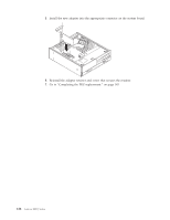
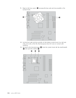
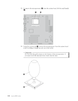
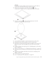
11. Remove the four screws 1 securing the heat sink and fan assembly to the system board. 12. Lift the heat sink and fan assembly off the failing system board. Lay the heat sink on its side so that the thermal grease does not come in contact with anything. 13. To remove the microprocessor 2 from the system board, lift the small handle 3 and open the retainer 1 . 126 Lenovo 3000 J Series
-
 1
1 -
2
-
3
-
4
-
5
-
6
-
7
-
8
-
9
-
10
-
11
-
12
-
13
-
14
-
15
-
16
-
17
-
18
-
19
-
20
-
21
-
22
-
23
-
24
-
25
-
26
-
27
-
28
-
29
-
30
-
31
-
32
-
33
-
34
-
35
-
36
-
37
-
38
-
39
-
40
-
41
-
42
-
43
-
44
-
45
-
46
-
47
-
48
-
49
-
50
-
51
-
52
-
53
-
54
-
55
-
56
-
57
-
58
-
59
-
60
-
61
-
62
-
63
-
64
-
65
-
66
-
67
-
68
-
69
-
70
-
71
-
72
-
73
-
74
-
75
-
76
-
77
-
78
-
79
-
80
-
81
-
82
-
83
-
84
-
85
-
86
-
87
-
88
-
89
-
90
-
91
-
92
-
93
-
94
-
95
-
96
-
97
-
98
-
99
-
100
-
101
-
102
-
103
-
104
-
105
-
106
-
107
-
108
-
109
-
110
-
111
-
112
-
113
-
114
-
115
-
116
-
117
-
118
-
119
-
120
-
121
-
122
-
123
-
124
-
125
-
126
-
 127
127 -
 128
128 -
 129
129 -
 130
130 -
 131
131 -
 132
132 -
 133
133 -
 134
134 -
 135
135 -
 136
136 -
 137
137 -
138
-
139
-
140
-
141
-
142
-
143
-
144
-
145
-
146
-
147
-
148
-
149
-
150
-
151
-
152
-
153
-
154
-
155
-
156
-
157
-
158
-
159
-
160
-
161
-
162
-
163
-
164
-
165
-
166
-
167
-
168
-
169
-
170
-
171
-
172
-
173
-
174
-
175
-
176
-
177
-
178
-
179
-
180
-
181
-
182
-
183
-
184
-
185
-
186
-
187
-
188
-
189
-
190
-
191
-
192
-
193
-
194
-
195
-
196
-
197
-
198
-
199
-
200
-
201
-
202
-
203
-
204
-
205
-
206
-
207
-
208
-
209
-
210
-
211
-
212
-
213
-
214
-
215
-
216
-
217
-
218
 |
 |

11.
Remove
the
four
screws
±1²
securing
the
heat
sink
and
fan
assembly
to
the
system
board.
12.
Lift
the
heat
sink
and
fan
assembly
off
the
failing
system
board.
Lay
the
heat
sink
on
its
side
so
that
the
thermal
grease
does
not
come
in
contact
with
anything.
13.
To
remove
the
microprocessor
±2²
from
the
system
board,
lift
the
small
handle
±3²
and
open
the
retainer
±1²
.
126
Lenovo
3000
J
Series