Lenovo J105 Hardware Maintenance Manual - Page 139
socket
 |
View all Lenovo J105 manuals
Add to My Manuals
Save this manual to your list of manuals |
Page 139 highlights
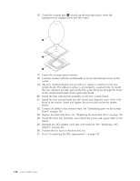
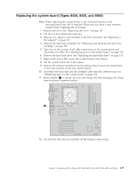
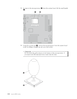
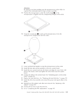
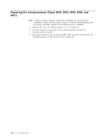
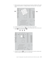
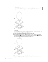
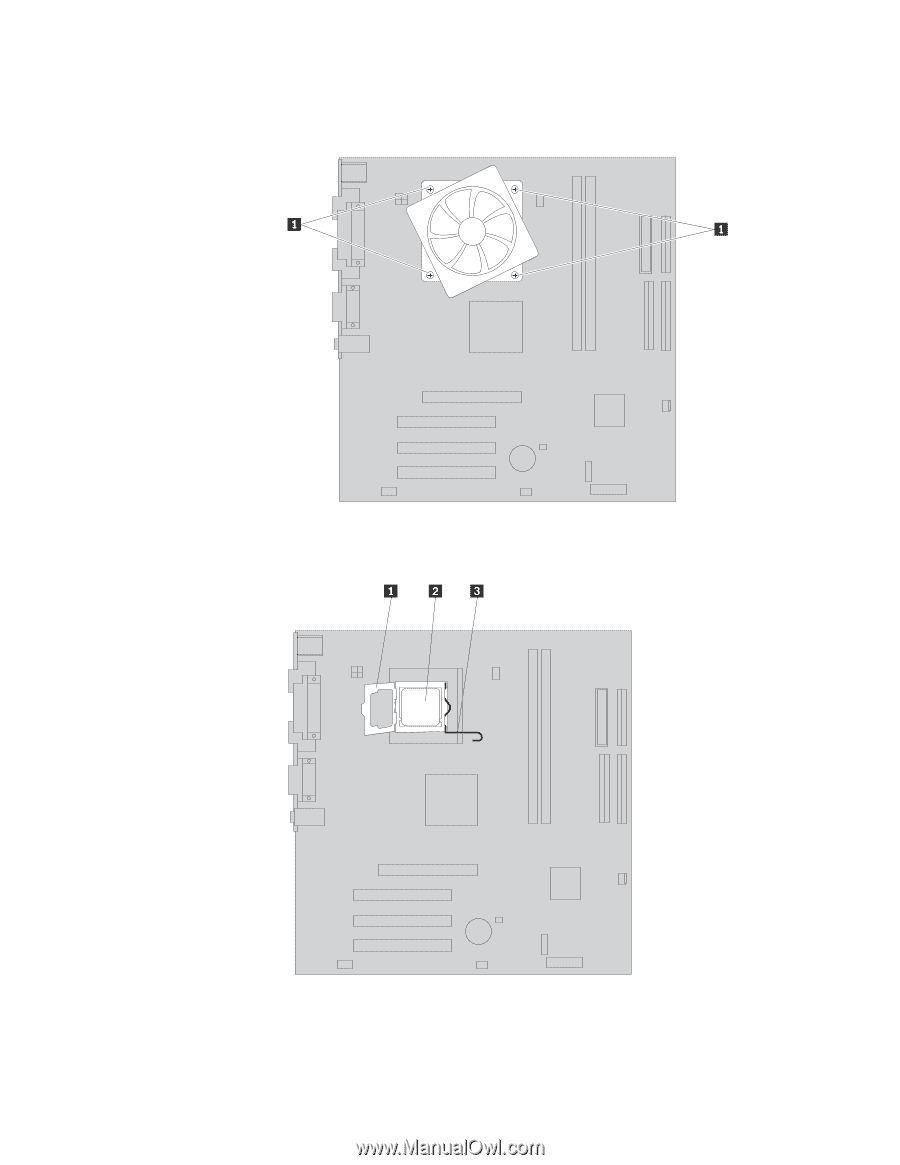
4. Remove the four screws securing the heat sink and fan assembly to the system board. Notice that there is a retention bracket on the back side of the system board. 5. Lift the heat sink and fan assembly off the failing system board. 6. To remove the microprocessor 2 from the failing system board, lift the small handle 3 and open the retainer 1 . 7. Using the vacuum pen 1 , remove the microprocessor from the system board socket by lifting it straight up and out of the socket. Chapter 9. Replacing FRUs (Types 8453, 8454, 8455, 8456, 8457, 8458, 8459, and 8460) 133
-
 1
1 -
2
-
3
-
4
-
5
-
6
-
7
-
8
-
9
-
10
-
11
-
12
-
13
-
14
-
15
-
16
-
17
-
18
-
19
-
20
-
21
-
22
-
23
-
24
-
25
-
26
-
27
-
28
-
29
-
30
-
31
-
32
-
33
-
34
-
35
-
36
-
37
-
38
-
39
-
40
-
41
-
42
-
43
-
44
-
45
-
46
-
47
-
48
-
49
-
50
-
51
-
52
-
53
-
54
-
55
-
56
-
57
-
58
-
59
-
60
-
61
-
62
-
63
-
64
-
65
-
66
-
67
-
68
-
69
-
70
-
71
-
72
-
73
-
74
-
75
-
76
-
77
-
78
-
79
-
80
-
81
-
82
-
83
-
84
-
85
-
86
-
87
-
88
-
89
-
90
-
91
-
92
-
93
-
94
-
95
-
96
-
97
-
98
-
99
-
100
-
101
-
102
-
103
-
104
-
105
-
106
-
107
-
108
-
109
-
110
-
111
-
112
-
113
-
114
-
115
-
116
-
117
-
118
-
119
-
120
-
121
-
122
-
123
-
124
-
125
-
126
-
127
-
128
-
129
-
130
-
131
-
132
-
133
-
 134
134 -
 135
135 -
 136
136 -
 137
137 -
 138
138 -
 139
139 -
 140
140 -
 141
141 -
 142
142 -
 143
143 -
 144
144 -
145
-
146
-
147
-
148
-
149
-
150
-
151
-
152
-
153
-
154
-
155
-
156
-
157
-
158
-
159
-
160
-
161
-
162
-
163
-
164
-
165
-
166
-
167
-
168
-
169
-
170
-
171
-
172
-
173
-
174
-
175
-
176
-
177
-
178
-
179
-
180
-
181
-
182
-
183
-
184
-
185
-
186
-
187
-
188
-
189
-
190
-
191
-
192
-
193
-
194
-
195
-
196
-
197
-
198
-
199
-
200
-
201
-
202
-
203
-
204
-
205
-
206
-
207
-
208
-
209
-
210
-
211
-
212
-
213
-
214
-
215
-
216
-
217
-
218
 |
 |
4.
Remove
the
four
screws
securing
the
heat
sink
and
fan
assembly
to
the
system
board.
Notice
that
there
is
a
retention
bracket
on
the
back
side
of
the
system
board.
5.
Lift
the
heat
sink
and
fan
assembly
off
the
failing
system
board.
6.
To
remove
the
microprocessor
±2²
from
the
failing
system
board,
lift
the
small
handle
±3²
and
open
the
retainer
±1²
.
7.
Using
the
vacuum
pen
±1²
,
remove
the
microprocessor
from
the
system
board
socket
by
lifting
it
straight
up
and
out
of
the
socket.
Chapter
9.
Replacing
FRUs
(Types
8453,
8454,
8455,
8456,
8457,
8458,
8459,
and
8460)
133