Panasonic AG-HMC70 Memory Card Camera Recorder - Page 20
DC input terminal [DC IN 7.3V], Input Level Selection Switches CH1/CH2
 |
UPC - 092281893525
View all Panasonic AG-HMC70 manuals
Add to My Manuals
Save this manual to your list of manuals |
Page 20 highlights
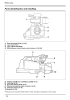
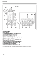
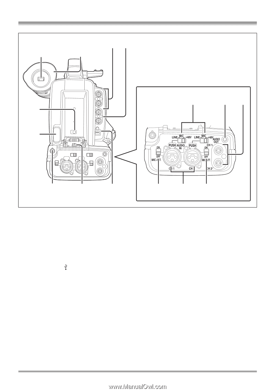
Before using 31 32 29 30 33 34 38 39 40 35 36 37 41 42 43 29) Viewfinder (l 42) 30) Eye cup (l 17) 31) Component Connectors (Y, PB, PR/BNC) (l 82) 32) Video Output Connector (BNC) (l 84) 33) DC input terminal [DC IN 7.3V] (l 32) 34) Battery Removal Button (l 30) 35) Headphone Connector [PHONE] (Mini jack) (l 68) 36) Battery Installation Slot (l 30) 37) USB terminal [ ] (l 86, 96) 38) Input Level Selection Switches (CH1/CH2) (l 59) 39) Recording lamp (rear) (l 104) 40) Audio Output Connectors (CH1/CH2) (l 82,84,85) 41) Microphone Attenuation Switch (CH1) (l 59) 42) Audio XLR Input Connector (l 59) 43) Microphone Attenuation Switch (CH2) (l 59) ≥The jack cover and cable holder have not been included in illustrations in this manual. 20
-
 1
1 -
2
-
3
-
4
-
5
-
6
-
7
-
8
-
9
-
10
-
11
-
12
-
13
-
14
-
 15
15 -
 16
16 -
 17
17 -
 18
18 -
 19
19 -
 20
20 -
 21
21 -
 22
22 -
 23
23 -
 24
24 -
 25
25 -
26
-
27
-
28
-
29
-
30
-
31
-
32
-
33
-
34
-
35
-
36
-
37
-
38
-
39
-
40
-
41
-
42
-
43
-
44
-
45
-
46
-
47
-
48
-
49
-
50
-
51
-
52
-
53
-
54
-
55
-
56
-
57
-
58
-
59
-
60
-
61
-
62
-
63
-
64
-
65
-
66
-
67
-
68
-
69
-
70
-
71
-
72
-
73
-
74
-
75
-
76
-
77
-
78
-
79
-
80
-
81
-
82
-
83
-
84
-
85
-
86
-
87
-
88
-
89
-
90
-
91
-
92
-
93
-
94
-
95
-
96
-
97
-
98
-
99
-
100
-
101
-
102
-
103
-
104
-
105
-
106
-
107
-
108
-
109
-
110
-
111
-
112
-
113
-
114
-
115
-
116
-
117
-
118
-
119
-
120
-
121
-
122
-
123
-
124
 |
 |
Before using
20
29) Viewfinder (
l
42)
30) Eye cup (
l
17)
31) Component Connectors (Y, P
B
, P
R
/BNC) (
l
82)
32) Video Output Connector (BNC) (
l
84)
33) DC input terminal [DC IN 7.3V] (
l
32)
34) Battery Removal Button (
l
30)
35) Headphone Connector [PHONE] (Mini jack) (
l
68)
36) Battery Installation Slot (
l
30)
37) USB terminal [
] (
l
86, 96)
38) Input Level Selection Switches (CH1/CH2) (
l
59)
39) Recording lamp (rear) (
l
104)
40) Audio Output Connectors (CH1/CH2) (
l
82,84,85)
41) Microphone Attenuation Switch (CH1) (
l
59)
42) Audio XLR Input Connector (
l
59)
43) Microphone Attenuation Switch (CH2) (
l
59)
≥
The jack cover and cable holder have not been included in illustrations in this manual.
29
33
34
35
36
37
41
42
43
38
39
40
30
31 32