Samsung HL-S5679W User Manual (ENGLISH) - Page 14
Rear Panel Jacks, DVI INPUT jack HDMI 1/DVI - power supply
 |
UPC - 036725256613
View all Samsung HL-S5679W manuals
Add to My Manuals
Save this manual to your list of manuals |
Page 14 highlights
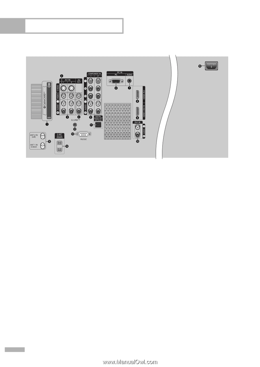
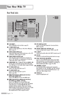
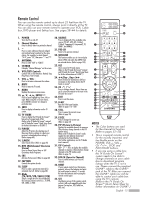
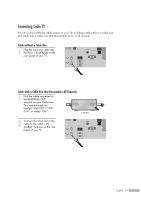
Your New Wide TV Rear Panel Jacks Œ CableCARDTM Insert a CableCARD into the slot. (Refer to page 22) ´ S-VIDEO INPUT jacks Connects an S-Video signal from an S-VHS, VCR or DVD player. (Refer to page 21) ˇ VIDEO/AUDIO INPUT jacks Connect video/audio signals from external sources, such as VCR or DVD players. (Refer to pages 21 and 25) ¨ VIDEO/AUDIO OUTPUT jacks Sends video/audio signals from the TV to an external source, such as a VCR. These jacks are available only in TV, Video and S-Video modes. (Refer to pages 21 and 27) ˆ COMPONENT IN 1, 2 jacks (Y, PB, PR, AUDIO L/R) Use these jacks to connect the component video/audio signals from a DVD player or a Set-Top Box. (Refer to pages 24 and 26) Ø PC VIDEO INPUT jack Connect to the video output jack on your PC. ∏ PC AUDIO INPUT jack Connect to the audio output jack on your PC. (Refer to page 132) " HDMI (High Definition Multimedia Interface) INPUT jacks (HDMI IN 2) Connect to the HDMI jack of a device with HDMI output. ' HDMI (High Definition Multimedia Interface)/ DVI INPUT jack (HDMI 1/DVI IN) Connect to the HDMI jack of a device with HDMI output. These inputs can also be used as a DVI connection with separate analog audio inputs. An optional HDMI/DVI cable will be necessary to make this connection. When using an optional HDMI/DVI adapter, the DVI analog audio inputs on your TV allow you to receive left and right audio from your DVI device. (Not compatible with PC) (Refer to pages 24 and 27) ˝ DVI AUDIO (L/R) IN Connect to the DVI audio output jack of an external device. (Refer to page 26) Ô DIGITAL AUDIO OUT (OPTICAL) jack Connect to a Digital Audio Component. (Refer to page 28) G-LINKTM Connect the IR controller cable to the G-LINKTM terminal on your TV. Ò RS232C Connection for professional linking network and service usage. Ú D-Net (IEEE1394) S400 MPEG Connect to external IEEE1394 digital products such as digital VCRs and camcorders. Two jacks are provided for this purpose, which allow for a high degree of flexibility for connecting your D-Net controlled system. (Refer to pages 116~130) Æ ANTENNA terminals Two independent cables or antennas can be connected to these terminals. Use "ANT 1 IN (CABLE)" and "ANT 2 IN (AIR)" terminals to receive a signal from VHF/UHF antennas or your cable system. (Refer to pages 18~20) ı POWER IN Connect the supplied power cord. English - 14
-
 1
1 -
2
-
3
-
4
-
5
-
6
-
7
-
8
-
 9
9 -
 10
10 -
 11
11 -
 12
12 -
 13
13 -
 14
14 -
 15
15 -
 16
16 -
 17
17 -
 18
18 -
 19
19 -
20
-
21
-
22
-
23
-
24
-
25
-
26
-
27
-
28
-
29
-
30
-
31
-
32
-
33
-
34
-
35
-
36
-
37
-
38
-
39
-
40
-
41
-
42
-
43
-
44
-
45
-
46
-
47
-
48
-
49
-
50
-
51
-
52
-
53
-
54
-
55
-
56
-
57
-
58
-
59
-
60
-
61
-
62
-
63
-
64
-
65
-
66
-
67
-
68
-
69
-
70
-
71
-
72
-
73
-
74
-
75
-
76
-
77
-
78
-
79
-
80
-
81
-
82
-
83
-
84
-
85
-
86
-
87
-
88
-
89
-
90
-
91
-
92
-
93
-
94
-
95
-
96
-
97
-
98
-
99
-
100
-
101
-
102
-
103
-
104
-
105
-
106
-
107
-
108
-
109
-
110
-
111
-
112
-
113
-
114
-
115
-
116
-
117
-
118
-
119
-
120
-
121
-
122
-
123
-
124
-
125
-
126
-
127
-
128
-
129
-
130
-
131
-
132
-
133
-
134
-
135
-
136
-
137
-
138
-
139
-
140
-
141
-
142
-
143
-
144
-
145
-
146
-
147
-
148
-
149
-
150
-
151
-
152
-
153
-
154
-
155
-
156
-
157
-
158
-
159
-
160
 |
 |