Samsung HL-S5679W User Manual (ENGLISH) - Page 26
Connecting a DTV Set-Top Box, Connecting to Y, PB, PR, Connecting to DVI (Digital Visual, P, Interface
 |
UPC - 036725256613
View all Samsung HL-S5679W manuals
Add to My Manuals
Save this manual to your list of manuals |
Page 26 highlights
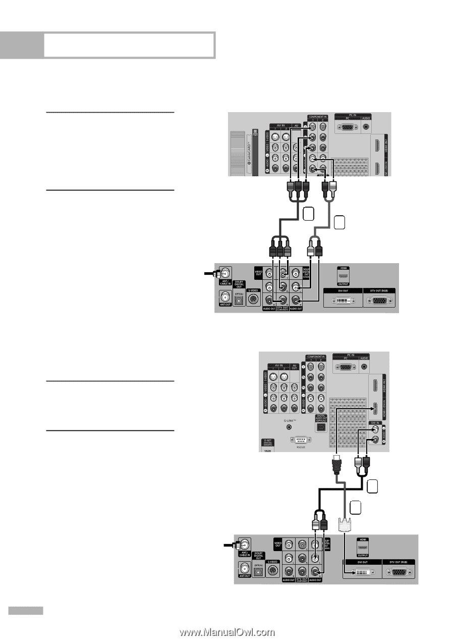
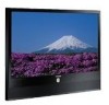
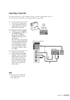
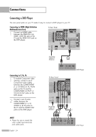
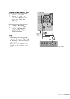
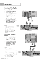
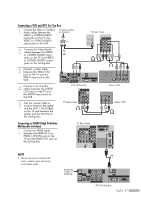
Connections Connecting a DTV Set-Top Box Connecting to Y, PB, PR 1 Connect a set of Component cables between the COMPONENT (1 or 2) VIDEO (Y, PB, PR) IN jacks on the TV and VIDEO (Y/PB/PR or Y/CB/CR) OUT jacks on the Set-Top Box. 2 Connect a set of audio cables between the COMPONENT (1 or 2) AUDIO (L, R) IN jacks on the TV and the AUDIO OUT jacks on the Set-Top Box. TV Rear Panel 1 2 NOTES • Please be sure to match the color coded input terminals and cable jacks. • Component Video separates the video into Y(Luminance (Brightness)), Pb (Blue) and Pr (Red) for enhanced video quality. Incoming Cable or Antenna Connecting to DVI (Digital Visual Interface) 1 Connect an HDMI/DVI cable between the HDMI 1/DVI IN jack on the TV and the DVI OUT jack on the Set-Top Box. 2 Connect a set of audio cables between the DVI AUDIO (L, R) IN jacks on the TV and the AUDIO OUT jacks on the Set-Top Box. NOTES • Requires a Cable Converter. • To use the TV Guide On ScreenTM, you have to connect the G-LINKTM cable. • Make sure the HDMI/DVI source's power is on, or you will be unable to select it in the TV menu's source list. • The HDMI 1/DVI IN jack is not compatible with PC. Incoming Cable or Antenna English - 26 DTV Set-Top Box TV Rear Panel 2 1 DTV Set-Top Box
-
 1
1 -
2
-
3
-
4
-
5
-
6
-
7
-
8
-
9
-
10
-
11
-
12
-
13
-
14
-
15
-
16
-
17
-
18
-
19
-
20
-
 21
21 -
 22
22 -
 23
23 -
 24
24 -
 25
25 -
 26
26 -
 27
27 -
 28
28 -
 29
29 -
 30
30 -
 31
31 -
32
-
33
-
34
-
35
-
36
-
37
-
38
-
39
-
40
-
41
-
42
-
43
-
44
-
45
-
46
-
47
-
48
-
49
-
50
-
51
-
52
-
53
-
54
-
55
-
56
-
57
-
58
-
59
-
60
-
61
-
62
-
63
-
64
-
65
-
66
-
67
-
68
-
69
-
70
-
71
-
72
-
73
-
74
-
75
-
76
-
77
-
78
-
79
-
80
-
81
-
82
-
83
-
84
-
85
-
86
-
87
-
88
-
89
-
90
-
91
-
92
-
93
-
94
-
95
-
96
-
97
-
98
-
99
-
100
-
101
-
102
-
103
-
104
-
105
-
106
-
107
-
108
-
109
-
110
-
111
-
112
-
113
-
114
-
115
-
116
-
117
-
118
-
119
-
120
-
121
-
122
-
123
-
124
-
125
-
126
-
127
-
128
-
129
-
130
-
131
-
132
-
133
-
134
-
135
-
136
-
137
-
138
-
139
-
140
-
141
-
142
-
143
-
144
-
145
-
146
-
147
-
148
-
149
-
150
-
151
-
152
-
153
-
154
-
155
-
156
-
157
-
158
-
159
-
160
 |
 |