Sanyo VDC-HD3300 VDC-HD3300 Manual
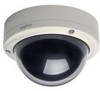
Sanyo VDC-HD3300 - Full HD 1080p Vandal Dome Camera Manual
 |
UPC - 086483075087
View all Sanyo VDC-HD3300 manuals
Add to My Manuals
Save this manual to your list of manuals |
Sanyo VDC-HD3300 manual content summary:
- Sanyo VDC-HD3300 | VDC-HD3300 Manual - Page 1
VDC-HD3300/HD300P VDC-HD3100/HD3100P Features of This Camera Specifications Name and Function of Each Component Connections Lens Installation Lens Adjustment Viewing Firmware Version Introduction1/15 - Sanyo VDC-HD3300 | VDC-HD3300 Manual - Page 2
supports network operation. By simply connecting a LAN cable to it, you can construct the most advanced network monitoring system. From the Web browser (Internet Explorer) installed on your PC, you can operate the camera via the network in an easy-to-use manner. In addition, it is a PoE software - Sanyo VDC-HD3300 | VDC-HD3300 Manual - Page 3
32× max) or Off VDC-HD3300P/VDC-HD3100P: 1/25, 1/50, 1/120, 1/250, 1/500, 1/1000, 1/2000, 1/4000, 1/10000D VDC-HD3300/VDC-3100: 1/30, 1/60, 1/100, 1/250, 1/500, 1/1000, 1/2000, 1/4000, 1/10000 Long exposure shutter (1×, 2×, 4×, 8×, 16×, 32×) DC iris lens supported Selectable between 2 camera setting - Sanyo VDC-HD3300 | VDC-HD3300 Manual - Page 4
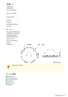
ambient temperature/humidity Power source Power consumption Weight Dimensions IP66 -10 to +50°C, 90% RH or less (no condensation) 12 to 15 VDC/24 VAC±10%, 50/60 Hz, PoE 4,6W, 18W (with heater turned on) 770 g Approvals: IP66/CE This unit has been certified to IP66 standards when properly installed - Sanyo VDC-HD3300 | VDC-HD3300 Manual - Page 5
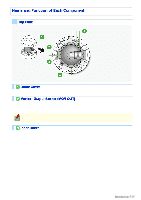
To remove the cover, remove the three screws using the supplied hex wrench. Connecting the camera and monitor using the supplied cable enables you to perform focus and iris adjustments while monitoring the live video. For details, see the "Connections" section. You can use crocodile clip connectors - Sanyo VDC-HD3300 | VDC-HD3300 Manual - Page 6
Press the REVERSE button ( 4 ) Not supported via network operation For details, see the "Installation Manual". Restarting camera Press the RESET button ( 5 ) CAMERA SETTINGS (CAMERA REBOOT) For details, refer to the "Viewing Firmware Viewing Firmware Version Version" section. OPTION SETTINGS - Sanyo VDC-HD3300 | VDC-HD3300 Manual - Page 7
base bracket. Use this socket to connect the camera to your PC to enable network operation. Use this cable to connect a 24 VAC or 12 VDC power supply. There is no power indicator on the camera. Alarm input cable: Connect an external switch, infrared sensor, or other device to detect alarm - Sanyo VDC-HD3300 | VDC-HD3300 Manual - Page 8
of your system. Improper connection may cause smoke or failures. Before attempting to connect each system component, carefully read the instruction manual that comes with it to familiarize yourself with the correct connection procedure. Alarm Input Terminal Connection Connect an alarm switch - Sanyo VDC-HD3300 | VDC-HD3300 Manual - Page 9
switching signal path, follow the steps below. ( (This function is supported only by VDC-HD3300P/VDC-HD3300.)) Under [DAY/NIGHT], set [DAY/NIGHT] to "COLOR" and the voltage at the 24-VAC/12-VDC terminals is within the operating range of the camera. When using PoE to power the camera, do not use - Sanyo VDC-HD3300 | VDC-HD3300 Manual - Page 10
to set port forwarding, please refer to your router's Instruction manual. To connect two or more cameras, on the NETWORK SETTINGS screen, assign them with port numbers that are different from that of the first camera. Using PoE This camera supports PoE (Power over Ethernet). This means that you can - Sanyo VDC-HD3300 | VDC-HD3300 Manual - Page 11
To perform focus adjustment with the camera, remove the dome cover, connect the supplied cable to the MON OUT socket of the camera, and connect a monitor to the camera using a video cable. ( A ) After adjustment, be sure to remove the monitor cable. You can use crocodile clip connectors instead of - Sanyo VDC-HD3300 | VDC-HD3300 Manual - Page 12
After installing the lens to the camera, you need to perform the following adjustments for the lens. A Angle of View/Focus Adjustment (FOCUS ASSIST) B Iris Adjustment (IRIS) Using network operation, you can use the focus assist function to adjust the focus. Use the focus assist function to - Sanyo VDC-HD3300 | VDC-HD3300 Manual - Page 13
FOCUSING" turns from black to orange. If the camera fails to automatically focus on the object, the status indicator ( A ) will indicate "ERROR". In this case, manually adjust the focus (in Step 3 ). 3 Press the NEAR/FAR button to adjust the focus. Adjust to set the FA bar ( B ) to the maximum level - Sanyo VDC-HD3300 | VDC-HD3300 Manual - Page 14
If the camera produces too dark, too bright, or other incorrect video images, adjust the lens iris. 1 Press the SET button for 2 seconds or more. The monitor now shows the SELECT MENU screen. On the SELECT MENU screen, all information is displayed in English. 2 Select [IRIS] using the NEAR/FAR - Sanyo VDC-HD3300 | VDC-HD3300 Manual - Page 15
] using the NEAR/FAR button and press the SET button. The monitor now shows the FIRMWARE VERSION screen. 3 Press the SET button for 2 seconds or more. The FIRMWARE VERSION screen closes. The FIRMWARE VERSION screen will close automatically if left idle for 5 minutes or more. Introduction 15/15 - Sanyo VDC-HD3300 | VDC-HD3300 Manual - Page 16
VDC-HD3300/HD300P VDC-HD3100/HD3100P From Connection to Network Operation Live Video Monitoring Alarm Detection and Output Software Information Configuration menu quick reference tables Quick Operation Guide1/10 - Sanyo VDC-HD3300 | VDC-HD3300 Manual - Page 17
to normal live video monitoring. 1 Connect the power cable to the power terminals. Use a 24-VAC or 12-VDC power supply. Do not turn on the camera until you complete all connections. 2 Connect the network (LAN) socket Turn on the camera. Live video appears on the monitor. Quick Operation Guide 2/10 - Sanyo VDC-HD3300 | VDC-HD3300 Manual - Page 18
camera from your PC's Web browser. Live video appears on the live screen. Now, you can perform all network operations from your PC. Quick Operation Guide 3/10 - Sanyo VDC-HD3300 | VDC-HD3300 Manual - Page 19
video using the buttons on the live screen control panel. The screenshot above shows the factory default settings for each video/image condition. Quick Operation Guide 4/10 - Sanyo VDC-HD3300 | VDC-HD3300 Manual - Page 20
A MASKING B DETECT 10SEC to 5MIN, CC (Retains an alarm state as long as the motion alarm persists.) A Disabling motion detection in masked areas Quick Operation Guide 5/10 - Sanyo VDC-HD3300 | VDC-HD3300 Manual - Page 21
screen. You can configure the camera to "automatically output alarm signals" or "remotely (manually) output alarm signals". You can configure the camera to automatically output an alarm signal when provided on the live screen to send alarm signals from the camera's Quick Operation Guide 6/10 - Sanyo VDC-HD3300 | VDC-HD3300 Manual - Page 22
TIME (Alarm output 5SEC (Ex.: Beeps a warning 10SEC to 5MIN, CC (Stops alarm output when time) for 5 sec.) Remote Alarm button is clicked.) Quick Operation Guide 7/10 - Sanyo VDC-HD3300 | VDC-HD3300 Manual - Page 23
camera includes all the supplied software. A H.264 Plug-in (Plug-in for monitoring live video as high-quality moving images) This plug-in software is required to display is designed for use with SANYO network cameras. This is a complete version of the VA-SW3050 series software, which offers all the - Sanyo VDC-HD3300 | VDC-HD3300 Manual - Page 24
the camera's IP address. Using SANYO's DDNS service. Using SSL communication. Streaming H.264 the camera from video viewer or similar software to view NETWORK SETTINGS live video and-white video modes ( (This function is supported only by VDC-HD3300P/VDCHD3300.)) Configuration Screen (Menu) E-MAIL - Sanyo VDC-HD3300 | VDC-HD3300 Manual - Page 25
the factory default settings Backing up or uploading settings Viewing the access log, system log, and operation log Configuration Screen (Menu) OPTION SETTINGS (FIRMWARE UPDATE) OPTION SETTINGS (FACTORY DEFAULT) OPTION SETTINGS (MENU BACKUP/MENU UPLOAD) OPTION SETTINGS (LOG) Quick Operation - Sanyo VDC-HD3300 | VDC-HD3300 Manual - Page 26
VDC-HD3300/HD300P VDC-HD3100/HD3100P Preparing Your Computer for Network Operation Setting Up IP Addresses Automatically (Auto IP Setup) Checking the operating environment Configue the network information on your PC Operation Privileges and Login Users Before You Begin Network Operation1/13 - Sanyo VDC-HD3300 | VDC-HD3300 Manual - Page 27
camera. If you have newly installed two or more cameras on your network, you can accomplish this by using the supplied "Auto IP Setup" software. 2 Check your operating environment 3 Connect the camera to the network to which your PC is also connected. 4 Configue the network information on your PC - Sanyo VDC-HD3300 | VDC-HD3300 Manual - Page 28
IP address overlap. The supplied "Auto IP Setup" software frees you from this burden by automatically assigning a unique Firmware Version" are not shown if the network board or other hardware is not supported. "IP Address", "Port", "SSL", and "Camera Title" are editable. (Refer to the "Manually - Sanyo VDC-HD3300 | VDC-HD3300 Manual - Page 29
cameras have overlapping IP addresses (indicated by a status of "CAUTION") or if you need to change a camera title, you can edit the displayed camera data manually as described below. Before You Begin Network Operation 4/13 - Sanyo VDC-HD3300 | VDC-HD3300 Manual - Page 30
1 Select the desired camera and click Manual setting . The camera information dialog box opens. 2 Make changes to the camera data and click EXECUTE . This transmits your changes to the camera. You can see the problem of IP address overlap has been resolved in the [Status] row of the list, which has - Sanyo VDC-HD3300 | VDC-HD3300 Manual - Page 31
system environment. Use Windows Update to keep the operating system and browser up-to-date. Note, however, that Internet Explorer 8 is not supported. In the cases below, configure the Internet Explorer's settings by clicking [Tool] and then [Internet Options]. When accessing the camera using SSL - Sanyo VDC-HD3300 | VDC-HD3300 Manual - Page 32
1 In [Control Panel], click [Network and Internet Connections]. The [Network and Internet Connections] dialog box opens. 2 Click [Network Connections]. The [Network Connections] dialog box opens. Under [LAN or High-Speed Internet], the icon representing your LAN interface (Ethernet adapter) - Sanyo VDC-HD3300 | VDC-HD3300 Manual - Page 33
4 In the [This connection uses the following items:] list box, select the [Internet Protocol (TCP/IP)] check box. Confirm that the [Internet Protocol (TCP/IP)] check box is selected. If deselected, select the check box. 5 Click [Properties]. The [Internet Protocol (TCP/IP) Properties] dialog box - Sanyo VDC-HD3300 | VDC-HD3300 Manual - Page 34
6 Select the [Use the following IP address:] radio button and specify the IP address, the subnet mask, and the default gateway. 7 Check the configured settings and click OK . You are now done with the TCP/IP configuration. Close all the dialog boxes that are open. 1 In [Control Panel], click [ - Sanyo VDC-HD3300 | VDC-HD3300 Manual - Page 35
2 Click [Manage network connections]. The [Network Connections] dialog box opens. 3 Double-click [Local Area Connection]. The [Local Area Connection Status] dialog box opens. 4 Click [Properties] and, in the confirmation dialog box, click [Continue]. The [Local Area Connection Properties] dialog box - Sanyo VDC-HD3300 | VDC-HD3300 Manual - Page 36
6 Click [Properties]. The [Internet Protocol Version 4 (TCP/IPv4) Properties] dialog box opens, with the [General] tab shown. 7 Select the [Use the following IP address:] radio button and specify the IP address and the subnet mask. 8 Check the configured settings and click OK . You are now done with - Sanyo VDC-HD3300 | VDC-HD3300 Manual - Page 37
The operation privileges of users who perform network operation are divided into 3 levels (admin, operator, and guest). Each user who attempts to access the camera will be authenticated by the user name and password at login and granted an appropriate operation privilege. Operation admin Monitor - Sanyo VDC-HD3300 | VDC-HD3300 Manual - Page 38
also provides simultaneous access to the camera from your Web browser. However, if the user who is using the software configures one of the following settings, the Web-based admin user will be disconnected from the camera. Camera Setting Normal Recording & Live Setting (JPEG) Live - Sanyo VDC-HD3300 | VDC-HD3300 Manual - Page 39
VDC-HD3300/HD300P VDC-HD3100/HD3100P Access the camera from your Web browser Live Screen Components Control panel Tool panel Working with Live Screen1/10 - Sanyo VDC-HD3300 | VDC-HD3300 Manual - Page 40
1 Start Internet Explorer. The supported Web browser is Internet Explorer Ver.6.0 SP2 or higher, or Internet Explorer Ver.7.0. 2 In the address bar, type the IP address of the camera and - Sanyo VDC-HD3300 | VDC-HD3300 Manual - Page 41
at a time from your Web browser. To access two or more cameras from your PC simultaneously, use the following software. Monitoring software "VA-SW3050Lite" (Supplied) Installing this software adds to your PC the capability to simultaneously access two or more cameras and monitor live video from all - Sanyo VDC-HD3300 | VDC-HD3300 Manual - Page 42
When you access and log into the camera successfully, the live screen appears. For details, refer to the linked information. Video display area ( A ) Control Panel ( B ) Tool Panel ( C ) 1 Current date and time Shows the current date and time based on the clock settings configured on the CLOCK - Sanyo VDC-HD3300 | VDC-HD3300 Manual - Page 43
Click the desired button depending on the purpose of your operation. Then, the corresponding screen and panels will appear. For details, refer to the linked information. MENU : Click this to display the configuration menu. LANGUAGE : Click this to display the language selection screen. DISPLAY : - Sanyo VDC-HD3300 | VDC-HD3300 Manual - Page 44
or rejecting the access to the camera from up to 10 PCs. OPTION 10 OPTION SETTINGS Perform operations such as updating the firmware, restoring the factory defaults, and backing up and uploading settings. Other Buttons Operation Buttons Function 1 HELP Provides an explanation of each function - Sanyo VDC-HD3300 | VDC-HD3300 Manual - Page 45
Click DISPLAY on the control panel to bring up the display control panel. : Panel is minimized. Clicking the button opens the panel. : Clicking the button closes the panel. SIZE The available options vary depending on your selection in [ASPECT RATIO] and your image/video compression format (JPEG/H. - Sanyo VDC-HD3300 | VDC-HD3300 Manual - Page 46
Shows the camera title you configured in [TITLE] on the CLOCK SETTINGS screen. The default camera title is "Network Camera". The color of the camera title changes depending on the alarm state as follows: Gray: Normal state Red: Alarm condition is being detected. When the camera title is shown in red - Sanyo VDC-HD3300 | VDC-HD3300 Manual - Page 47
1 Click the Capture button on the tool panel. The captured still image appears in a separate window. This button is not available when you are monitoring H.264 video. When a captured still image is shown, the live screen continues to display moving images in the video display area. 2 Right-click on - Sanyo VDC-HD3300 | VDC-HD3300 Manual - Page 48
ALARM OUT TIME]. When the set output duration has elapsed, the camera stops sending the alarm signal automatically and the button returns to white. Manual Stop The manual stop method is applied if you have selected "CC" in [ALARM OUT TIME]. Click one of the remote alarm buttons shown in orange. Then - Sanyo VDC-HD3300 | VDC-HD3300 Manual - Page 49
VDC-HD3300/HD300P VDC-HD3100/HD3100P NETWORK SETTINGS CLOCK SETTINGS USER SETTINGS CODEC/STREAMING SETTINGS CAMERA SETTINGS ALARM SETTINGS E-MAIL SETTINGS FTP SETTINGS SECURITY SETTINGS OPTION SETTINGS Working with Administrator Configuration Screens1/50 - Sanyo VDC-HD3300 | VDC-HD3300 Manual - Page 50
Click NETWORK in the configuration menu to display the NETWORK SETTINGS screen. On this screen, configure the following settings as required. A Configuring basic network settings (NETWORK) B Configuring DDNS setting (DDNS) C Configuring HTTP settings D Configuring RTSP/RTP settings E Configuring - Sanyo VDC-HD3300 | VDC-HD3300 Manual - Page 51
camera to apply the changes. Using SANYO's DDNS service, you can connect to the camera service, configure the following settings. Specify your DNS server address under [DNS SETTINGS] on this screen. Configure the port forwarding on your router. (For details, refer to your router's instruction manual - Sanyo VDC-HD3300 | VDC-HD3300 Manual - Page 52
1 On the LOG IN screen, enter the user name and password you wrote down and click Login . The Domain Name registration/change screen appears. SANYO DDNS service site URL: https://www.ddns-sanyosecurity.com 2 Enter the domain name you want to use and click Submit . The domain name is registered with - Sanyo VDC-HD3300 | VDC-HD3300 Manual - Page 53
SSL communication is enabled, you will be presented with a security warning dialog box when attempting to access the camera. However, this is not a problem and you can continue the operation by clicking [Yes]. If the message "This page contains both secure and nonsecure items..." appears, follow the - Sanyo VDC-HD3300 | VDC-HD3300 Manual - Page 54
, between 9874 and 10000, between 38087 and 38214, and between 49026 and 49152). If you intend to access the camera from video viewer or similar software, you may name each stream (access name) as you like for easy identification. In [ACCESS NAME], type the access name (up to 32 alphanumeric - Sanyo VDC-HD3300 | VDC-HD3300 Manual - Page 55
Click CLOCK in the configuration menu to display the CLOCK SETTINGS screen. Before you start network operation, you need to configure the clock settings on this screen. A Configuring camera title B Configuring clock date/time and display style C Configuring time zone and daylight saving mode D - Sanyo VDC-HD3300 | VDC-HD3300 Manual - Page 56
automatically selected according to the [TIME ZONE] setting, you can change it manually. NO USE: Disables the daylight saving mode. USE: Enables the daylight saving Internet, select "LOGIN (PC)" or, using the supplied monitoring software "VA-SW3050Lite", enable the clock adjustment function (24-hour - Sanyo VDC-HD3300 | VDC-HD3300 Manual - Page 57
1 In [CLOCK ADJUST], select "ON (NTP)". 2 Configure the required settings shown below and click SET . 1 To automatically adjust the clock time every day, in [TIME TO SYNCHRONIZE], select the 24-hour time to which you want to adjust the clock (for example, "10:30"). 2 To adjust the clock to the - Sanyo VDC-HD3300 | VDC-HD3300 Manual - Page 58
The clock time will not be adjusted if the difference between the set time and the current time exceeds the range of -29 to +30 minutes. If you set [CLOCK ADJUST] to "ALARM IN1", the ALARM IN1 terminal will serve dedicatedly as a time adjustment terminal, so you can see only the item [POLARITY] in [ - Sanyo VDC-HD3300 | VDC-HD3300 Manual - Page 59
Click USER in the configuration menu to display the USER SETTINGS screen. On this screen, configure the user authentication check at login. Required operation privilege: admin, operator Disabling the authentication check at login allows all users to log into the camera without authentication. In [ - Sanyo VDC-HD3300 | VDC-HD3300 Manual - Page 60
each operation privilege and click SET . The available options vary depending on the model used. VDC-HD3300/VDC-HD3100: 0.1ips, 0.2ips, 0.5ips, 1ips, 3ips, 5ips, 10ips, 15ips, 30ips VDC-HD3300P/VDC-HD3100P: 0.1ips, 0.2ips, 0.5ips, 1ips, 2.5ips, 5ips, 8ips, 12.5ips, 25ips Working with Administrator - Sanyo VDC-HD3300 | VDC-HD3300 Manual - Page 61
. 3 In [FRAME RATE], select the frame rate of the stream. The available options vary depending on the model used. VDC-HD3300/VDC-HD3100: 15ips, 30ips VDC-HD3300P/VDC-HD3100P: 12.5ips, 25ips Depending on the configured resolution, the available options for image quality and frame rate may be limited - Sanyo VDC-HD3300 | VDC-HD3300 Manual - Page 62
Click CAMERA in the configuration menu to display the CAMERA SETTINGS screen. The CAMERA SETTINGS screen includes a sub menu from which you can access 14 camera settings to configure the monitoring and other conditions of the camera. Required operation privilege: admin, operator The CAMERA SETTINGS - Sanyo VDC-HD3300 | VDC-HD3300 Manual - Page 63
between color and black-and-white video modes depending on the luminance of the target. ( (This function is supported only by VDC-HD3300P/VDC-HD3300.)) VIEW 8 APERTURE Configure the contour compensation function. VIEW VIVID COLOR 9 EFFECT Configure the color saturation compensation function - Sanyo VDC-HD3300 | VDC-HD3300 Manual - Page 64
object. If [DAY/NIGHT] is set to "AUTO", the electronic sensitivity boosting function will work only for black/white video images. (For VDC-HD3300P/VDC-HD3300) [SHUTTER] is set to "OFF", preventing you from configuring the electronic shutter setting ("SHORT" or "LONG"). No motion sensor type can be - Sanyo VDC-HD3300 | VDC-HD3300 Manual - Page 65
3200: Fixed white balance (for indoors) 5600: Fixed white balance (for outdoors) FLUORESCENT: Fixed white balance (for fluorescent lighting) MWB: Manual white balance The configured settings will be applied to "CAM1" or "CAM2", whichever you selected under [VIEW]. Auto trace white balance - Sanyo VDC-HD3300 | VDC-HD3300 Manual - Page 66
2 Drag the mouse over the live video image to select the area you want to mask. The masked area is indicated by blue-bordered grid cells each containing the letter "M". You can mask more than one portion of the live image. You can click one grid cell after another to set or cancel the masked area - Sanyo VDC-HD3300 | VDC-HD3300 Manual - Page 67
fluorescent lighting (Fixes the color temperature to 4200K.) Use the following procedure to manually adjust the gain values for the red and blue signals. 1 In [WHITE ]. Multi-spot evaluative metering compensates for the backlighting problem by evaluating the photometry of the entire screen. Working - Sanyo VDC-HD3300 | VDC-HD3300 Manual - Page 68
backlighting and click SET . 0 (low brightness compensation) to 15 (high brightness compensation) Center-weighted average metering compensates for the backlighting problem by measuring the photometry of the specified area intensively. Configure the position and size of the center metering area. 1 In - Sanyo VDC-HD3300 | VDC-HD3300 Manual - Page 69
SET and then BACK . The settings are saved and you return to the sub menu. You can use light source masking to compensate for backlighting problems with human or other objects in the subject, by masking the light source in a bright background. 1 In [BLC], select "MASKING" and click SET . The BLC - Sanyo VDC-HD3300 | VDC-HD3300 Manual - Page 70
], select the desired shutter speed and click SET . The available options vary depending on the model used. VDC-HD3300P/VDC-HD3100P: 25, 50, 120, 250, 500, 1000, 2000, 4000, 10000 VDC-HD3300/VDC-HD3100: 30, 60, 100, 250, 500, 1000, 2000, 4000, 10000 Each of the above shutter speed values represents - Sanyo VDC-HD3300 | VDC-HD3300 Manual - Page 71
moving object. Configure the video signal gain value automatically or manually. Automatically configuring gain value using AGC Manually configuring gain value Auto Gain Control (AGC) is a the mode set for [DAY/NIGHT]. (For VDCHD3300P/VDC-HD3300) Working with Administrator Configuration Screens 23/50 - Sanyo VDC-HD3300 | VDC-HD3300 Manual - Page 72
video modes when an external control signal is received Fixing camera to color or black-and-white video mode This function is supported only by VDC-HD3300P/VDC-HD3300. The configured settings will be applied to "CAM1" or "CAM2", whichever you selected under [VIEW]. In AUTO mode, turning off the - Sanyo VDC-HD3300 | VDC-HD3300 Manual - Page 73
: ADJ: Sets a low luminance level (to increase the time during which the camera operates in the color mode). Enables the manual adjustment of the luminance level. Manually Configuring Mode-Switching Luminance Level (ADJ) You can select a luminance level between 1 and 7 for both the color to black - Sanyo VDC-HD3300 | VDC-HD3300 Manual - Page 74
1 In [DAY/NIGHT], select "COLOR". 2 In [EXT ALARM], select the desired alarm input terminal and click SET . ALARM IN1: Sets the ALARM IN1 terminal as the Day/Night switching terminal. ALARM IN2: Sets the ALARM IN2 terminal as the Day/Night switching terminal. OFF: Fixing Camera to Color Video - Sanyo VDC-HD3300 | VDC-HD3300 Manual - Page 75
Select "ON" in [APERTURE] and an appropriate correction level in [LEVEL] and click SET . The higher the correction level, the greater the correction effect. 1 to 15 The configured settings will be applied to "CAM1" or "CAM2", whichever you selected under [VIEW]. Use the color saturation - Sanyo VDC-HD3300 | VDC-HD3300 Manual - Page 76
subject distance or ambient temperature, the deterioration of the lens and installation environment, and the like that have been caused over the years. 1 Select the [MANUAL] check box. Now you can operate the NEAR , FAR , and ONE PUSH buttons. Working with Administrator Configuration Screens 28/50 - Sanyo VDC-HD3300 | VDC-HD3300 Manual - Page 77
the camera fails to focus on the subject, the status indicator ( A ) will show "ERROR". In this case, manually adjust the focus (in Step 3 ). 3 Click NEAR / FAR to focus on the subject. 4 Deselect the [MANUAL] check box. Be sure to deselect the check box to prevent the loss of focus due to wrong - Sanyo VDC-HD3300 | VDC-HD3300 Manual - Page 78
The mask setting screen shows the video at the angle of view that you see on the live screen. 2 Drag the mouse over the live video image to select the area you want to mask. A mask pattern appears over the selected area. You can set up to eight mask patterns on the screen. To select a mask pattern, - Sanyo VDC-HD3300 | VDC-HD3300 Manual - Page 79
6 Click SET and then BACK . The settings are saved and you return to the sub menu. Working with Administrator Configuration Screens 31/50 - Sanyo VDC-HD3300 | VDC-HD3300 Manual - Page 80
terminal. In this case, the [SET VALUE] column of [ALARM IN1] shows "CLOCK IN" in, allowing you to select a value in [POLARITY] only. With VDC-HD3300P/VDC-HD3300: if you set [DAY/NIGHT] to "COLOR" and [EXT ALARM] to "ALARM IN1" or "ALARM IN2" under [DAY/NIGHT SETTINGS] on the CAMERA SETTINGS screen - Sanyo VDC-HD3300 | VDC-HD3300 Manual - Page 81
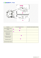
To configure the ALARM IN2 terminal to detect an alarm condition, select "ON" in [ALARM IN2] and specify the input conditions for it in the same way as for the ALARM IN1 terminal. This camera offers the built-in motion sensor function that automatically detects motion in the subject. The motion - Sanyo VDC-HD3300 | VDC-HD3300 Manual - Page 82
To switch the alarm detection method, in [MOTION ALARM], click the desired radio button. 3 Drag the mouse over live video/image to select the area you want to mask. The masked area is indicated by blue-bordered grid cells each containing the letter "M". You can mask as many areas as you want without - Sanyo VDC-HD3300 | VDC-HD3300 Manual - Page 83
The terminal will not accept subsequent alarm signals until the set duration expires. The alarm state will be retained for at least 5 seconds even if the motion is instantaneous. The configured duration value will be reset to the factory default value if you change any setting on the ALARM SETTINGS - Sanyo VDC-HD3300 | VDC-HD3300 Manual - Page 84
5 In [SENSITIVITY], select the detection sensitivity. You can adjust the detection sensitivity to prevent unwanted detection. The higher the value, the lower the sensitivity. 1 to 9 Checking how the motion sensor works Click TEST ( 2 ). If any motion is detected in a grid cell in the detection area, - Sanyo VDC-HD3300 | VDC-HD3300 Manual - Page 85
1 In [ALARM OUT1], select "ON". 2 In [POLARITY], select the signal polarity of the alarm output terminal. NO (Normally Open): The terminal is normally open and closes when an alarm signal is output. NC (Normally Closed): The terminal is normally closed and opens when an alarm signal is output. 3 In - Sanyo VDC-HD3300 | VDC-HD3300 Manual - Page 86
1 In [ALARM OUT1], select "REMOTE". Selecting "REMOTE" does not cause the terminal to output an alarm signal automatically even if an alarm condition is detected. 2 In [POLARITY], select the signal polarity of the alarm output terminal. NO (Normally Open): The terminal is normally open and closes - Sanyo VDC-HD3300 | VDC-HD3300 Manual - Page 87
MAIL], select "ON" to enable the e-mail transmission function. 2 In [SSL], select "ON" to use SSL communication. If your e-mail server supports SSL, you can encrypt e-mail transmission. 3 Configure your e-mail server. Type the following information on your e-mail server. A SMTP SERVER ADDRESS Type - Sanyo VDC-HD3300 | VDC-HD3300 Manual - Page 88
1 In [MAIL ADDRESS], type the recipient e-mail addresses. Here, you can type up to five e-mail addresses (up to 64 alphanumeric characters for each). 2 Select the check box for each e-mail address to which you want to send e-mails. You can send e-mails to the selected e-mail address(es). 3 To attach - Sanyo VDC-HD3300 | VDC-HD3300 Manual - Page 89
2 In [USER ID] and [PASSWORD], type the user ID and password, respectively. Type the user ID (up to 48 alphanumeric characters) and password for authentication (up to 20 alphanumeric characters). 3 In [POP3 SERVER ADDRESS], type your POP3 server address and click SET . If you selected "POP3" in [ - Sanyo VDC-HD3300 | VDC-HD3300 Manual - Page 90
An e-mail consists of the following portions. Subject Camera Title Data and time Camera's IP address Message (TEXT) The camera title, date and time, IP address will be included automatically. 1 In [SUBJECT], type the subject (title) of the e-mail. You can type up to 32 alphanumeric characters. 2 In - Sanyo VDC-HD3300 | VDC-HD3300 Manual - Page 91
Click FTP in the configuration menu to display the FTP SETTINGS screen. If you want to record images from the camera to an FTP server via the network, configure the FTP server settings and the image transmission conditions on this screen. A Configuring FTP server settings B Configuring transmission - Sanyo VDC-HD3300 | VDC-HD3300 Manual - Page 92
to other than "INTERVAL"): [FILE NAME] + [yy_mm_dd_hh_mm_ss] + [alarm_factor] + [0001 (Serial No.).jpg] If no file name is specified, the system will enter "sanyo" for the [FILE NAME]. * To use a temporary file, set [TEMPORARY FILE] to "USE". This causes each image to be stored as a temporary file - Sanyo VDC-HD3300 | VDC-HD3300 Manual - Page 93
The setting values are interlocked among E-MAIL SETTINGS, and FTP SETTINGS screens. (Note that the setting configured most recently will take precedence.) B If you selected "ALARM IN1/2", "MOTION", or "ALARM OUT1/2" ... In [DURATION], select the image transmission duration. 5SEC, 10SEC, 20SEC, 40SEC - Sanyo VDC-HD3300 | VDC-HD3300 Manual - Page 94
Click SECURITY in the configuration menu to display the SECURITY SETTINGS screen. Configuring the security function on this screen enables you to restrict the PCs that can access the camera. Required operation privilege: admin, operator1 1 In [SECURITY FUNCTION], select "ON". 2 In [DEFAULT POLICY], - Sanyo VDC-HD3300 | VDC-HD3300 Manual - Page 95
4 Click SET . The settings are saved. Working with Administrator Configuration Screens 47/50 - Sanyo VDC-HD3300 | VDC-HD3300 Manual - Page 96
SET to reboot the camera system. You can update the camera's firmware to the latest version. 1 Click SET . The FIRMWARE UPDATE screen appears. 2 Click BROWSE and select the firmware updater file. 3 Click EXECUTE . The firmware update process starts. When the update process is completed, the camera - Sanyo VDC-HD3300 | VDC-HD3300 Manual - Page 97
Do not perform any operations on the screen or turn off the camera until the firmware update process is completed. While the firmware is being updated, all camera functions stop working temporarily. You can restore all the settings you have configured to the factory default settings. In [NETWORK - Sanyo VDC-HD3300 | VDC-HD3300 Manual - Page 98
A ACCESS LOG Shows the history of access to the camera in chronological order (up to 100 entries). Date and time, user name, authentication check result (OK/NG), connection destination IP address B SYSTEM LOG Shows a history of system operation in chronological order (up to 200 entries). Working - Sanyo VDC-HD3300 | VDC-HD3300 Manual - Page 99
VDC-HD3300/HD300P VDC-HD3100/HD3100P Accessing the Camera Control Panel/Tool Panel CAMERA SETTINGS Displaying LIVE video Transmitting Image Data Others Q&A1/10 - Sanyo VDC-HD3300 | VDC-HD3300 Manual - Page 100
camera by entering a URL (or router global address and camera port number) registered with the dynamic DNS service or a URL that is compliant with the global address. I cannot access the camera from the Internet. . For the configuration method, refer to your router's instruction manual. Q&A 2/10 - Sanyo VDC-HD3300 | VDC-HD3300 Manual - Page 101
access from the Internet. For the configuration method, refer to your router's instruction manual. 5 The IP address you entered is a local address (the one you , select [FIRMWARE VERSION] to check the firmware version. Using the supplied "Auto IP Setup" software, execute a camera search. Q&A 3/10 - Sanyo VDC-HD3300 | VDC-HD3300 Manual - Page 102
Buttons on the control panel/tool panel do not respond. 1 You do not have the required operation privilege. Some buttons on the control panel/tool panel are operable only when you have an adequate operation privilege. Log in as a user with an adequate operation privilege. 2 You have not configured - Sanyo VDC-HD3300 | VDC-HD3300 Manual - Page 103
UP] in [IRIS] to "OFF". I cannot turn off the AGC. 1 If [DAY/NIGHT] is set to "AUTO", you cannot set [AGC] to "OFF". (When using VDC-HD3300P/VDC -HD3300) Set [DAY/NIGHT] to "COLOR" or "B/W". 2 You cannot set [AGC] to "OFF" when [SENSE UP] in [IRIS] is set to "ON". Set [SENSE UP - Sanyo VDC-HD3300 | VDC-HD3300 Manual - Page 104
between the different versions. Install the H.264 Plug-In included in the supplied CD-ROM or the latest H.264 Plug-In you can download from SANYO CCTV System Web page. 4 The Web browser you are using for accessing the camera is configured to connect to the Internet via proxy server. Some - Sanyo VDC-HD3300 | VDC-HD3300 Manual - Page 105
Check the power supply status and/or the network environment. The video image is distorted and cannot be displayed correctly. 1 The maximum bit rate for video streaming is configured with a value higher than the network bandwidth. Lower the resolution and/or image quality. 2 The performance of the - Sanyo VDC-HD3300 | VDC-HD3300 Manual - Page 106
to the monitored environment. Or, on the CAMERA SETTINGS screen, select [AUTO] for [DAY/NIGHT] and enable the [DAY/NIGHT] mode. (When using VDC-HD3300P/VDC-HD3300) 2 The color quality for your PC monitor is configured to less than 16 bits. On the [Display Properties] -[Settings] tab, configure the - Sanyo VDC-HD3300 | VDC-HD3300 Manual - Page 107
server requires authentification. Contact your network administrator and change the authentication setting according to the SMTP server setting. This camera supports the two authentication methods, "SMTP" and "POP3 (POP before SMTP)". 4 Transfer is blocked by the "Outbound Port 25 Blocking (OP25B - Sanyo VDC-HD3300 | VDC-HD3300 Manual - Page 108
has been interrupted due to power off, network fault, or other problem during the process. Redo the upgrade by proceeding as follows. 1 Turn on the camera again. 2 Access the camera again. 3 Check the firmware version on [FIRMWARE UPDATE] in OPTION SETTINGS screen. * If the version number is updated - Sanyo VDC-HD3300 | VDC-HD3300 Manual - Page 109
VDC-HD3300/HD300P VDC-HD3100/HD3100P Copyright Notice How to use this manual Copyright Notice/How to Use This Manual1/8 - Sanyo VDC-HD3300 | VDC-HD3300 Manual - Page 110
This instruction manual is copyrighted by SANYO Electric Co., Ltd. No materials contained in this manual may be reproduced Project" must not be used to * endorse or promote products derived from this software without * prior written permission. For written permission, please contact * openssl-core@ - Sanyo VDC-HD3300 | VDC-HD3300 Manual - Page 111
must retain the following * acknowledgment: * "This product includes software developed by the OpenSSL Project * for use in the OpenSSL Toolkit (INCLUDING, BUT * NOT LIMITED TO, PROCUREMENT OF SUBSTITUTE GOODS OR SERVICES; * LOSS OF USE, DATA, OR PROFITS; OR BUSINESS INTERRUPTION Use This Manual 3/8 - Sanyo VDC-HD3300 | VDC-HD3300 Manual - Page 112
(INCLUDING, BUT NOT LIMITED TO, PROCUREMENT OF SUBSTITUTE GOODS * OR SERVICES; LOSS OF USE, DATA, OR PROFITS; OR BUSINESS INTERRUPTION) * OR OTHERWISE) ARISING IN ANY WAY * OUT OF THE USE OF THIS SOFTWARE, EVEN IF ADVISED OF THE POSSIBILITY OF * SUCH DAMAGE. * * The How to Use This Manual 4/8 - Sanyo VDC-HD3300 | VDC-HD3300 Manual - Page 113
This window shows a table of contents. The headline of the topic currently opened at the main window is highlighted, so the current location among the manual can be easily confirmed. 2 TITLE window This window shows the headline of the current topic. This TITLE window never scrolls not to hide the - Sanyo VDC-HD3300 | VDC-HD3300 Manual - Page 114
linked to the top of the page. Click on this mark to jump to the top of the page. Copyright Notice/How to Use This Manual 6/8 - Sanyo VDC-HD3300 | VDC-HD3300 Manual - Page 115
to the associated settings that must be configured on other menu screens. Caution: Indicates prohibited or restricted operating and setting instructions. This manual uses the following notations to present user-interface related information: Information such as the screen title is represented in all - Sanyo VDC-HD3300 | VDC-HD3300 Manual - Page 116
of this screenshot is to show you the factory default value for each setting item provided on the screen. Copyright Notice/How to Use This Manual 8/8
-
 1
1 -
 2
2 -
 3
3 -
 4
4 -
 5
5 -
 6
6 -
 7
7 -
8
-
9
-
10
-
11
-
12
-
13
-
14
-
15
-
16
-
17
-
18
-
19
-
20
-
21
-
22
-
23
-
24
-
25
-
26
-
27
-
28
-
29
-
30
-
31
-
32
-
33
-
34
-
35
-
36
-
37
-
38
-
39
-
40
-
41
-
42
-
43
-
44
-
45
-
46
-
47
-
48
-
49
-
50
-
51
-
52
-
53
-
54
-
55
-
56
-
57
-
58
-
59
-
60
-
61
-
62
-
63
-
64
-
65
-
66
-
67
-
68
-
69
-
70
-
71
-
72
-
73
-
74
-
75
-
76
-
77
-
78
-
79
-
80
-
81
-
82
-
83
-
84
-
85
-
86
-
87
-
88
-
89
-
90
-
91
-
92
-
93
-
94
-
95
-
96
-
97
-
98
-
99
-
100
-
101
-
102
-
103
-
104
-
105
-
106
-
107
-
108
-
109
-
110
-
111
-
112
-
113
-
114
-
115
-
116
 |
 |
VDC-HD3300/HD300P
VDC-HD3100/HD3100P
Features of This Camera
Specifications
Name and Function of Each Component
Connections
Lens Installation
Lens Adjustment
Viewing Firmware Version
Introduction1/15