Sanyo VDC-HD3300 VDC-HD3300 Manual - Page 9
Alarm Output Terminal Connection, Connection to 24 VAC power supply, Connection to 12 VDC power - vdc hd3300p
 |
UPC - 086483075087
View all Sanyo VDC-HD3300 manuals
Add to My Manuals
Save this manual to your list of manuals |
Page 9 highlights
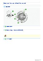
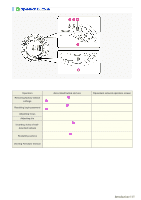
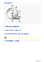
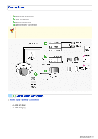
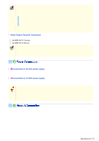
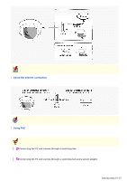
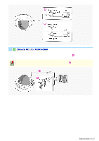
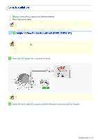
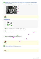
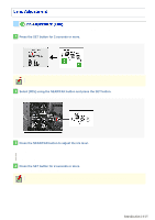
After connecting an alarm device, configure the input conditions for the corresponding alarm input cable via network operation on the ALARM SETTINGS screen. To use the alarm input cable as Day/Night switching signal path, follow the steps below. ( (This function is supported only by VDC-HD3300P/VDC-HD3300.)) Under [DAY/NIGHT], set [DAY/NIGHT] to "COLOR" and select the cable you want to use in [EXT ALARM]. On the ALARM SETTINGS screen, in [POLARITY], select the signal polarity of the alarm input terminal. Connecting an external switch to ALARM IN1 allows you to set the system clock by operating the switch. To set the system clock, configure the [CLOCK IN] setting on the CLOCK SETTINGS screen. Alarm Output Terminal Connection Connect a buzzer, lamp, or other alarm device to the alarm output cable. ALARM OUT1: Orange ALARM OUT2: Brown After connecting an alarm device, configure the output conditions for the corresponding alarm output cable via network operation on the ALARM SETTINGS screen. Configuration of alarm output terminal is also possible via remote operation. For that, set [ALARM OUT] to "REMOTE" on the ALARM SETTINGS (ALARM OUT) screen. Connect the power terminals (24 VAC/12 VDC) of the camera to a power supply. A Connection to 24 VAC power supply Although the power terminals have no polarity, the earth grounding wire must be connected to the GND (earth grounding) terminal. B Connection to 12 VDC power supply Note the polarity (+/-) of the power terminals when connecting the camera to a 12 VDC power supply. Incorrect polarity may cause damage to the camera. Be sure to use an 18AWG or thicker wire power cable. A voltage drop may occur depending on the thickness of the power cable. If you must use a long power cable, determine the cable type by ensuring that the voltage at the 24-VAC/12-VDC terminals is within the operating range of the camera. When using PoE to power the camera, do not use the camera's power terminals. This camera is designed so that you can use all of its functions via network operation. By connecting the network (LAN) socket of the camera to your PC using a LAN cable, you can configure and operate it from the Web browser installed on your PC. Introduction 9/15
-
 1
1 -
2
-
3
-
 4
4 -
 5
5 -
 6
6 -
 7
7 -
 8
8 -
 9
9 -
 10
10 -
 11
11 -
 12
12 -
 13
13 -
 14
14 -
15
-
16
-
17
-
18
-
19
-
20
-
21
-
22
-
23
-
24
-
25
-
26
-
27
-
28
-
29
-
30
-
31
-
32
-
33
-
34
-
35
-
36
-
37
-
38
-
39
-
40
-
41
-
42
-
43
-
44
-
45
-
46
-
47
-
48
-
49
-
50
-
51
-
52
-
53
-
54
-
55
-
56
-
57
-
58
-
59
-
60
-
61
-
62
-
63
-
64
-
65
-
66
-
67
-
68
-
69
-
70
-
71
-
72
-
73
-
74
-
75
-
76
-
77
-
78
-
79
-
80
-
81
-
82
-
83
-
84
-
85
-
86
-
87
-
88
-
89
-
90
-
91
-
92
-
93
-
94
-
95
-
96
-
97
-
98
-
99
-
100
-
101
-
102
-
103
-
104
-
105
-
106
-
107
-
108
-
109
-
110
-
111
-
112
-
113
-
114
-
115
-
116
 |
 |
