Sharp PN-T322B Service Manual
Sharp PN-T322B Manual
 |
View all Sharp PN-T322B manuals
Add to My Manuals
Save this manual to your list of manuals |
Sharp PN-T322B manual content summary:
- Sharp PN-T322B | Service Manual - Page 1
SERVICE MANUAL CODE : 00ZPNT321SME2 LCD MONITOR/ TOUCH-PANELINTEGRATED DISPLAY PN-T321 MODEL PN-T322B CONTENTS ■ LEAD-FREE SOLDER CHAPTER 1. OUTLINE OF THE PRODUCT 1 - 1 CHAPTER 2. INSTALLATION, ADJUSTMENT, SETTING 2 - 1 CHAPTER 3. CONTROLLING THE MONITOR WITH A PC . . . . . 3 - 1 CHAPTER 4. - Sharp PN-T322B | Service Manual - Page 2
REAR COVER 3 SPEAKER UNIT 4 LED DRIVER PWB 5 INLET HARNESS/AC SWITCH 6 POWER SUPPLY PWB 7 TEMPERATURE SENSOR PWB 8 I/F PWB 9 LCD MODULE 10 KEY PWB 11 TOUCH PANEL ASSEMBLY (PN-T322B) 7 - 1 7 - 3 7 - 4 7 - 5 7 - 6 7 - 8 7 - 8 7 - 9 7 - 13 7 - 15 7 - 16 CHAPTER 8. TROUBLESHOOTING 1 THE POWER IS NOT - Sharp PN-T322B | Service Manual - Page 3
CHAPTER 9. HARDWARE DESCRIPTIONS 1 SYSTEM DESCRIPTION 2 FUNCTIONS 3 PERFORMANCE SPECIFICATIONS 4 BLOCK DIAGRAM 5 TOUCH PANEL (PN-T322B) 9 - 1 9 - 3 9 - 3 9 - 4 9 - 5 ii - Sharp PN-T322B | Service Manual - Page 4
"LF" marks indicated on the PWB's and the Service Manual mean "Lead-Free" solder. Thealphabet following the LF . DISPOSE OF USED BATTERIES ACCORDING TO THE INSTRUCTIONS CAUTION DOUBLE POLE/NEUTRAL FUSING The battery supplied YOUR LOCAL SHARP DEALER OR AUTHORIZED SERVICE REPRESENTATIVE FOR ASSISTANCE - Sharp PN-T322B | Service Manual - Page 5
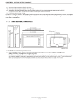
OUTLINE OF THE PRODUCT 1. SPECIFICATIONS 1 - 1. OUTLINE Model PN-T321 PN-T322B LCD component 32" Class [31-1/2 inch (80 cm) diagonal] TFT LCD area inch (mm) --- 27 x 15 (685.7 x 380.3) Touch Panel PC connector --- USB (1.1 compliant) Power supply --- Supplied from USB Position - Sharp PN-T322B | Service Manual - Page 6
from these values in individual units. 1 - 2. DIMENSIONAL DRAWINGS PN-T322B 2-7/16 [62] 1-1/2 [38] PN-T321 1-15/16 [49.1] 1 [25.3] 18-13/16 wall-mount bracket that complies with the VESA-compatible mounting method. SHARP recommends using M6 screws and tighten the screws. Note that screw - Sharp PN-T322B | Service Manual - Page 7
--- *1 Displays a reduced image, except in Dot by Dot. In Dot by Dot, the image will be cut down to panel size then displayed. *2 Displays as an AV signal (1280 x 720p). *3 Displays as an AV signal (1920 x 1080p). Yes Yes Yes Yes Yes Yes Yes Yes Yes Yes PN-T321/T322B OUTLINE OF THE PRODUCT 1 - 3 - Sharp PN-T322B | Service Manual - Page 8
. Do not reproduce it without permission. n Setup Manual: 1 n Vertical sticker (Operation panel): 1 n Vertical sticker (Logo): 1 n USB flash drive cover: 1 n USB flash drive cover screw (+): 1 (PN-T321) n USB flash drive cover screw (-): 1 (PN-T322B) n Cover Sharp logo: 1 Place this sticker onto the - Sharp PN-T322B | Service Manual - Page 9
+ No. Function 11 TMDS clock shield 12 TMDS clock- 13 N.C. 14 N.C. 15 SCL 16 SDA 17 DDC/CEC GND 18 +5V 19 Hot-plug detection PN-T321/T322B OUTLINE OF THE PRODUCT 1 - 5 - Sharp PN-T322B | Service Manual - Page 10
control sensor MEMO n Use a pointed object such as a pen tip to press the switches at the operation panel. 2 3 4 5 REFERENCE CHART OF POWER LAMP LIGHTING STATUS Lighting Status Green lamp is lit. Green cause of the temperature increase is removed. PN-T321/T322B OUTLINE OF THE PRODUCT 1 - 6 - Sharp PN-T322B | Service Manual - Page 11
H PC D-SUB input terminal I PC/AV DVI-D input terminal J PC/AV HDMI input terminal K USB cable (for touch panel: PN-T322B) 2 K 6 7 8 9 F G H I J ■ REMOTE CONTROL UNIT 1 2 7 3 8 4 5 9 6 1 Signal transmitter 2 POWER button 3 MUTE button Turns off the volume temporarily. Press the MUTE - Sharp PN-T322B | Service Manual - Page 12
unit, it may interfere with proper operation. n Do not use it with the remote control of other equipment such as air conditioner, stereo components, etc. PN-T321/T322B OUTLINE OF THE PRODUCT 1 - 8 - Sharp PN-T322B | Service Manual - Page 13
-click in Touch Screen Calibration Utility.For details, see the Touch Panel Driver Operation Manual. 3Refer to page 2 - 11 "3 - 3. ADJUSTING THE TOUCH PANEL". DRAG-AND-DROP Same action as drag-and-drop with a mouse finger, double-tap will not take place. PN-T321/T322B OUTLINE OF THE PRODUCT 1 - 9 - Sharp PN-T322B | Service Manual - Page 14
an obstacle between the sensor and your finger. n If the USB cable becomes disconnected, the touch panel may not operate correctly after the cable is reconnected. In this case, restart your computer. n display or lighting further away, or adjust the angle. PN-T321/T322B OUTLINE OF THE PRODUCT 1 - 10 - Sharp PN-T322B | Service Manual - Page 15
the characteristics of the software, and is not a malfunction. n Depending on the original image size, black bands may remain at the edges of the screen. PN-T321/T322B OUTLINE OF THE PRODUCT 1 - 11 - Sharp PN-T322B | Service Manual - Page 16
PN-T322B, use a fan to remain the ambient temperature in the above range. n Temperature condition may change when using the display together with the optional equipments recommended by SHARP sensor or buttons. Logo Operation panel n Place this sticker onto the SHARP logo to cover the logo. - Sharp PN-T322B | Service Manual - Page 17
the power outlet before connecting/disconnecting cables. Also, read the manual of the equipment to be connected. n Be careful not and output terminals may cause malfunctions and the other problems. MEMO n Images may not be displayed properly PN-T321/T322B INSTALLATION, ADJUSTMENT, SETTING 2 - 2 - Sharp PN-T322B | Service Manual - Page 18
the PC to match the monitor's communication settings as follows. Baud rate Data length Parity bit Stop bit Flow control 9600bps 8 bits None 1 bit None PN-T321/T322B INSTALLATION, ADJUSTMENT, SETTING 2 - 3 - Sharp PN-T322B | Service Manual - Page 19
(12mm) (H). n To remove the USB flash drive cover, reverse the procedure. Using excessive force may break the claws. Exercise caution. CAUTION n The operation manual says, "When assembling/disassembling the USB memory cover, do not touch the screws except for the black ones." The user must be note - Sharp PN-T322B | Service Manual - Page 20
in the [Monitor] folder. The adjustment pattern will appear. Adjust the screen automatically or manually. 2 - 1. AUTOMATIC ADJUSTMENT When you use the PC D-SUB input terminal to display with e and d.) TEMPERATURE ALERT (Adjust with e and d.) PN-T321/T322B INSTALLATION, ADJUSTMENT, SETTING 2 - 5 - Sharp PN-T322B | Service Manual - Page 21
AV signal input) COLORS (AV signal input) SHARPNESS (AV signal input) NOISE REDUCTION (AV 10 -10 - +10 -10 - +10 As shown in the left column ENGLISH FRANCAIS JAPANESE DSUB D D D D D D D D PN-T321/T322B DVI- COMPO- VIDEO HDMI USB DI NENT D D D D D (AV) D D (AV) D D (AV) D D D D - Sharp PN-T322B | Service Manual - Page 22
EFFECT RANDOM TRANSITION EFFECT INTERVAL *2 SHORT MEDIUM1 MEDIUM2 LONG *1 In the PN-T321, some firmware versions may allow selection of ENGLISH/FRANCAIS only. *2 In the PN-T321, some firmware versions may allow selection of SHORT/MEDIUM/LONG. PN-T321/T322B DVI- COMPO- VIDEO HDMI USB DI NENT - Sharp PN-T322B | Service Manual - Page 23
TINT (AV signal input) 30 COLORS (AV signal input) 30 SHARPNESS (AV signal input) 4 NOISE REDUCTION (AV signal input) MIDDLE TRANSITION EFFECT INTERVAL *1 *1 In the PN-T321, the default may be MEDIUM in some firmware versions. MEDIUM2 PN-T321/T322B INSTALLATION, ADJUSTMENT, SETTING 2 - 8 - Sharp PN-T322B | Service Manual - Page 24
SCREEN MENU PICTURE AUTO CLOCK PHASE H-POS V-POS RESET CONTRAST BLACK LEVEL TINT COLORS SHARPNESS NOISE REDUCTION COLOR MODE WHITE BALANCE (Adjust with e and d.) (Adjust with e automatically if no operation is performed for about 15 seconds. PN-T321/T322B INSTALLATION, ADJUSTMENT, SETTING 2 - 9 - Sharp PN-T322B | Service Manual - Page 25
" (Touch Panel Driver). MEMO n "xxxx" shows the version. 8 ) Click "Next". Follow the on-screen instructions to install the touch panel driver. n When time you use the touch panel, start the Touch Screen Calibration Utility and perform calibration. PN-T321/T322B INSTALLATION, ADJUSTMENT, SETTING 2 - Sharp PN-T322B | Service Manual - Page 26
the display screen size to "WIDE" or "NORMAL". n The touch panel cannot be used when the size is set to other than the above screen " to open the settings. Follow the on-screen instructions. 2 Setup 3 Display 4 Restore Factory Defaults n PN-T321/T322B INSTALLATION, ADJUSTMENT, SETTING 2 - 11 - Sharp PN-T322B | Service Manual - Page 27
taskbar and click "Exit". 2 ) Disconnect the USB cable. 3 ) Select "Control Panel" from the "Start" menu. 4 ) Click "Uninstall a program". n If you are (or "Allow"). 6 ) Remove "NextWindow 2500 Drivers" (Touch Panel Driver). Follow the on-screen instructions. n When the "User Account Control" screen - Sharp PN-T322B | Service Manual - Page 28
Be sure to input 4 characters for the parameter. Pad with spaces (" ") if necessary. (" " is a return code (0DH, 0AH or 0DH)) Wrong : VOLM30 . Right : VOLM 30 . PN-T321/T322B CONTROLLING THE MONITOR WITH A PC 3 - 1 - Sharp PN-T322B | Service Manual - Page 29
. VOLM0020 OK INPS0001 WAIT OK Interval of 100 ms or more MEMO n When executing ALL RESET, set the timeout period to 30 seconds or longer. PN-T321/T322B CONTROLLING THE MONITOR WITH A PC 3 - 2 - Sharp PN-T322B | Service Manual - Page 30
DVI-D, D-SUB input only) --- ■ SETUP MENU Function Command Direction Parameter Reply Control/Response contents *1 THERMAL SENSOR STDR WR 0 1 LANDSCAPE (Horizontal orientation) --- SETTING 1 1 PORTRAIT (Vertical orientation) --- PN-T321/T322B CONTROLLING THE MONITOR WITH A PC 3 - 3 - Sharp PN-T322B | Service Manual - Page 31
POWER button ● Main power off by the main power switch ● Standby mode by RS-232C ● Waiting mode by No Signal ● Standby mode by abnormal temperature ● PN-T321/T322B CONTROLLING THE MONITOR WITH A PC 3 - 4 - Sharp PN-T322B | Service Manual - Page 32
the latest. 3Refer to page 6 - 2 "2. EDID WRITING PROCEDURES". 4 ) Each service part has the firmware written in it. If necessary, the firmware should be updated to 3Refer to page 5 - 6 "9. TEMPERATURE MONITOR SETTING PROCEDURES". PN-T321/T322B IMPORTANT INFORMATION FOR SERVICING THE DISPLAY 4 - 1 - Sharp PN-T322B | Service Manual - Page 33
UPDATA Firmware Update Procedures (via RS-232C) Firmware Update Procedures (via USB) EDID WRITING TOUCH PANEL INSPECTION TOOL PN-T321/T322B | | | (T322B) PN-325 (Previous Model PN-V601 (Reference --- --- | | --- --- PN-T321/T322B IMPORTANT INFORMATION FOR SERVICING THE DISPLAY 4 - 2 - Sharp PN-T322B | Service Manual - Page 34
item with [VOL+ ( 2 )] [VOL- ( 4 )] button. 3 ) Adjust it with the [BRIGHT- ( 1 )] [BRIGHT+ ( 3 )] button. 4 ) Press [MENU] button to return to the previous screen sequentially, terminating the operation. PN-T321/T322B SERVICE MENU/VARIOUS SETTING TOOL OPERATING PROCEDURES 5 - 1 - Sharp PN-T322B | Service Manual - Page 35
run in the USB mode.) 1 ) Enter the "SERVICE MENU 2" mode. 2 ) Select "AGING" with [VOL " · " in the SERVICE MENU2 or FACTORY RESET is the factory preset values. 1 ) Display the SERVICE MENU 2. 2 ) Select "FACTORY RESET" with EDID write protect. 1 ) Display the SERVICE MENU2. 2 ) Select [EDID WRITE - Sharp PN-T322B | Service Manual - Page 36
User Account in the Control Panel. ■ USE INSTRUCTIONS 1 ) Execute "ServiceToolsLauncher.exe" in the folder where the service tool is extracted. 2 ) Once the service tool is booted, press Write EDID data in the display. PN-T321/T322B SERVICE MENU/VARIOUS SETTING TOOL OPERATING PROCEDURES 5 - 3 - Sharp PN-T322B | Service Manual - Page 37
START-UP OF THE SERIAL NUMBER SETTING TOOL Press [Serial Number] button of the Service Tool Launcher. 7 - 3. SERIAL NUMBER SETTING PROCEDURES RS-232C cable Straight cable display information, and check the serial number. PN-T321/T322B SERVICE MENU/VARIOUS SETTING TOOL OPERATING PROCEDURES 5 - 4 - Sharp PN-T322B | Service Manual - Page 38
column of USAGE TIME. To enter the SERVICE MENU 1, press and hold [SIZE] button on the remote controller for 5 sec, and press the buttons in the sequence of [BRIGHT- ( 1 )], [VOL- ( 4 )], [BRIGHT+ ( 3 )] and [VOL+ ( 2 )]. PN-T321/T322B SERVICE MENU/VARIOUS SETTING TOOL OPERATING PROCEDURES 5 - 5 - Sharp PN-T322B | Service Manual - Page 39
OF THE TEMPERATURE WATCH SETTING TOOL 1 ) Press [Temp Watch] button of the Service Tool Launcher screen. RS-232C cable Straight cable (D-SUB 9 pin female-female) CAUTION the readout information in an appro- priate file. PN-T321/T322B SERVICE MENU/VARIOUS SETTING TOOL OPERATING PROCEDURES 5 - 6 - Sharp PN-T322B | Service Manual - Page 40
time has been reset at the time of replacing the panel or the like. MEMO n The temperature watch setting data PN-T322B Installation Orientation Brightness down temperature (Level 5 of brightness) Shutdown temperature Landscape installation 58 Portrait installation 58 62 62 PN-T321/T322B SERVICE - Sharp PN-T322B | Service Manual - Page 41
Follow the on-screen instructions to install the program. ■ USE INSTRUCTIONS 1 ) Select [ Lite is launched, press appropriate buttons and inspect a touch panel. Buttons Pixel Map, Aperture, Auto Cam, Draw Test, Finalise PN-T321/T322B SERVICE MENU/VARIOUS SETTING TOOL OPERATING PROCEDURES 5 - 8 - Sharp PN-T322B | Service Manual - Page 42
. Follow the instruction, and touch the corner 1left top3 2right top3 3right bottom3 4left bottom in that order. If any operation isn't done for some seconds, the following timeout error window is displayed. In this case, click "Aperture" button and inspect again. PN-T321/T322B SERVICE MENU/VARIOUS - Sharp PN-T322B | Service Manual - Page 43
boards. If the result has no problem, the following window is displayed. Click it and the peration is finished. After the finalization, a log file is saved to PC. LOG FILE FOLDER: \Program Files\NextWindow\USB_Settings_Lite\data PN-T321/T322B SERVICE MENU/VARIOUS SETTING TOOL OPERATING PROCEDURES - Sharp PN-T322B | Service Manual - Page 44
X=180 in above graph) corresponds to left/right bottom of the screen. A touch panel unit amplifies the sensor information, and if "Y > 50", touching can be detected is "1275", Input "2500-0001275". PN-T321/T322B SERVICE MENU/VARIOUS SETTING TOOL OPERATING PROCEDURES 5 - 11 Sense area of camera - Sharp PN-T322B | Service Manual - Page 45
PN-T322B, copy the firmware version up file "PNT322B.Vxxbin" to the root directory (folder) of the USB memory in the file name of "PNT322B press the [DISPLAY] button of the remote control. 6 ) Confirm the version in SERVICE MENU 1. Press and hold [SIZE] for about 5 seconds, and press the arrow - Sharp PN-T322B | Service Manual - Page 46
2. OPERATING PROCEDURES 1 ) Connect the jig to the PC. 2 ) Press [EDID] button of the Service Tool Launcher. 3 ) Write the EDID of the I/F PWB connector. Select "PNxxxxx" in the column of -PROTECT OF EDID BY THE SERIAL COMMAND". PN-T321/T322B FIRMWARE UPDATA PROCEDURES/EDID WRITING PROCEDURES 6 - 2 - Sharp PN-T322B | Service Manual - Page 47
EDID error screen, the display returns to the window of 5). Then writing of another set can be performed continuously. 15) Turn off the main power. PN-T321/T322B FIRMWARE UPDATA PROCEDURES/EDID WRITING PROCEDURES 6 - 3 - Sharp PN-T322B | Service Manual - Page 48
to confirm that there is "ECP printer port (LPT1)." 1 ) Open the system of the Control Panel. 2 ) Open the System and Maintenance, and click the Device Manager. 3 ) Click the already "0378 - 037F," there is no need to change.) PN-T321/T322B FIRMWARE UPDATA PROCEDURES/EDID WRITING PROCEDURES 6 - 4 - Sharp PN-T322B | Service Manual - Page 49
returned, the connection is proper. 8 ) Send the EDWP command. Enter "EDPW1230" and press [Enter] key. If "OK" is returned, the EDID write-protect is canceled. PN-T321/T322B FIRMWARE UPDATA PROCEDURES/EDID WRITING PROCEDURES 6 - 5 - Sharp PN-T322B | Service Manual - Page 50
(EDID) SW2 : AUTO SW3 : 1502A SW4 : 1502A Serial (PROGRAM) MANUAL T1620 T1620 Left, right, right, right with the parallel connector on the (EDID) SW2 : AUTO SW3 : 1502A SW4 : 1502A Serial (PROGRAM) MANUAL T1620 T1620 Left, right, right, right with the parallel connector on the upper - Sharp PN-T322B | Service Manual - Page 51
service with the Display laid and with a protective sheet spread over the LCD panel. 1. PWB AND WIRING DIAGRAM ■ PN-T321 10 1 2 34 A B D C No. Parts name A LED driver 0QP0000000022 0QP0000000029 0QP0000000026 0QP0000000028 0QP0000000027 PN-T321/T322B DISASSEMBLY AND ASSEMBLY 7 - - Sharp PN-T322B | Service Manual - Page 52
CHAPTER 7. DISASSEMBLY AND ASSEMBLY ■ PN-T322B 10 1 2 34 F A D B C No. Parts name A LED driver PWB B Power supply PWB C Temperature sensor PWB D Main PWB E Key PWB F Touch panel assembly 9 Parts code 0QP0000000036 0QP0000000035 0QP0000000037 0QP1000000015 0QP0000000038 DUNT-1854MPZZ - Sharp PN-T322B | Service Manual - Page 53
(silver)) and 2pcs of screw D (3 x 4 (silver)), and then remove the Rear Cover. Screw A x 6 Screw B x 7 Screw C x 6 Screw D x 2 CAUTION n In the PN-T322B, be careful of the USB cable when removing the rear cover. SCREW TIGHTENING TORQUE n Screw A, B: 0.7 - 0.9N•m n Screw C: 0.5 - 0.6N•m n Screw - Sharp PN-T322B | Service Manual - Page 54
the harness. Remove the Speaker Unit. Red/Black White/Black Binding band x 3 2 connectors Fixing tape of the harness Screw x 4 CAUTION SCREW TIGHTENING TORQUE n 0.167 - 0.196N•m PN-T321/T322B DISASSEMBLY AND ASSEMBLY 7 - 4 - Sharp PN-T322B | Service Manual - Page 55
CHAPTER 7. DISASSEMBLY AND ASSEMBLY 4. LED DRIVER PWB 1 ) Unscrew 4pcs of screws (4 x 6 (black)), and then remove the angle. drive PWB. 3 ) Unscrew 4pcs of screws (3 x 6 (silver)), and remove the LED driver PWB. Remove the harness from the saddle. 4 connectors Screw x 4 CAUTION NOTE FOR DISASSEMBLY - Sharp PN-T322B | Service Manual - Page 56
B (3 x 6 (silver)), and remove the AC inlet/ AC switch assy. AC inlet/ AC switch assy Screw B x 2 Cable band Screw A x 2 CAUTION SCREW TIGHTENING TORQUE n 0.5 - 0.6N•m Connector Plate PN-T321/T322B DISASSEMBLY AND ASSEMBLY 7 - 6 - Sharp PN-T322B | Service Manual - Page 57
on the right side and it is in the OFF state. Black 4 connectors Red Screw B x 1 CAUTION SCREW TIGHTENING TORQUE n Screw A: 0.118 - 0.176N•m n Screw B: 0.26 - 0.32N•m PN-T321/T322B DISASSEMBLY AND ASSEMBLY 7 - 7 - Sharp PN-T322B | Service Manual - Page 58
connector of the temperature sensor PWB. Unscrew 1pc of screw (3 x 6 (silver)), and remove the temperature sensor PWB. Connecter Screw CAUTION SCREW TIGHTENING TORQUE n 0.167 - 0.196N•m PN-T321/T322B DISASSEMBLY AND ASSEMBLY 7 - 8 - Sharp PN-T322B | Service Manual - Page 59
CHAPTER 7. DISASSEMBLY AND ASSEMBLY 8. I/F PWB ■ PN-T321 1 ) Unscrew 4pcs of screw A (4 x 6 (black)), and remove the angle. Unscrew 2pcs of screw B (3 are attached horizontally as shown in the illustration. SCREW TIGHTENING TORQUE n 0.5 - 0.6N•m PN-T321/T322B DISASSEMBLY AND ASSEMBLY 7 - 9 - Sharp PN-T322B | Service Manual - Page 60
CAUTION SCREW TIGHTENING TORQUE n 0.5 - 0.6N•m 3 ) Unscrew 6pcs of hexagonal screws, and remove the I/F PWB. I/F PWB assy I/F PWB CAUTION SCREW TIGHTENING TORQUE n 0.35 - 0.45N•m Hexagonal screw x 6 PN-T321/T322B DISASSEMBLY AND ASSEMBLY 7 - 10 - Sharp PN-T322B | Service Manual - Page 61
CHAPTER 7. DISASSEMBLY AND ASSEMBLY ■ PN-T322B 1 ) Remove four screws A (4 x 6, Black) and four screws B (3 x 6, Silver), and remove the angle. Disconnect SCREW TIGHTENING TORQUE n Screw A: 0.7 - 0.9N•m n Screw B: 0.5 - 0.6N•m n Screw C, D: 0.5 - 0.6N•m PN-T321/T322B DISASSEMBLY AND ASSEMBLY 7 - 11 - Sharp PN-T322B | Service Manual - Page 62
as the I/F PWB assembly. Touch panel PWB assy Screw x 5 6 connectors Lock release Aluminum tape FFC I/F PWB assy CAUTION n The touch panel PWB assembly is connected with the FFC PWB CAUTION SCREW TIGHTENING TORQUE n 0.35 - 0.45N•m Hexagonal screw x 6 PN-T321/T322B DISASSEMBLY AND ASSEMBLY 7 - 12 - Sharp PN-T322B | Service Manual - Page 63
CHAPTER 7. DISASSEMBLY AND ASSEMBLY 9. LCD MODULE ■ PN-T321 1 ) Remove the FFC together with the fixing tape from the LCD module. Unscrew 2pcs Key FFC Screw B x 4 Screw D x 6 CAUTION SCREW TIGHTENING TORQUE n 0.167 - 0.196N•m Screw A x 2 Screw C x 4 PN-T321/T322B DISASSEMBLY AND ASSEMBLY 7 - 13 - Sharp PN-T322B | Service Manual - Page 64
CHAPTER 7. DISASSEMBLY AND ASSEMBLY ■ PN-T322B 1 ) Remove the FFC together with the fixing tape from the LCD module. Unscrew 2pcs of screw A A, C: 0.7 - 0.9N•m n Screw B: 0.5 - 0.6N•m Plate Fixing tape x 5 Key FFC Screw B x 4 Screw A x 2 Screw C x 4 PN-T321/T322B DISASSEMBLY AND ASSEMBLY 7 - 14 - Sharp PN-T322B | Service Manual - Page 65
AND ASSEMBLY 10. KEY PWB ■ PN-T321 1 ) Remove the tape. Remove the key PWB. Remove the FFC. Tape Key PWB Lock release FFC FFC ■ PN-T322B 1 ) Remove the key PWB cover. Remove the key PWB. Remove the FFC. Key PWB cover Key PWB FFC Lock release FFC PN-T321/T322B DISASSEMBLY AND ASSEMBLY 7 - 15 - Sharp PN-T322B | Service Manual - Page 66
CHAPTER 7. DISASSEMBLY AND ASSEMBLY 11. TOUCH PANEL ASSEMBLY (PN-T322B) 1 ) Remove the rear cover. 3Refer to page 7 - 3 "2. REAR COVER". and remove the front cabinet from the machine. 3Refer to page 7 - 5 "4. LED DRIVER PWB". Slide in the arrow direction of the engraved mark to remove. Bezel x 3 - Sharp PN-T322B | Service Manual - Page 67
and remove the touch panel assembly. 3Refer to page 7 - 8 "6. POWER SUPPLY PWB". Fixing tape x 2 Angle(Top side) Angle(Lower side) Touch panel assembly Screw A x , first attach the angle (lower side) and then attach the touch panel assembly, and slide the angle (upper side) in the arrow direction - Sharp PN-T322B | Service Manual - Page 68
CHAPTER 8. TROUBLESHOOTING No. ITEM 1 THE POWER IS NOT TURNED ON (THE LED DOES NOT LIGHT UP) 2 THE REMOTE CONTROLLER DOES NOT WORK 3 the abnormal part with a new one. Replace the abnormal part with a new one. Replace the abnormal part with a new one. PN-T321/T322B TROUBLESHOOTING 8 - 1 - Sharp PN-T322B | Service Manual - Page 69
CHAPTER 8. TROUBLESHOOTING 2. THE REMOTE CONTROLLER DOES NOT WORK Any problem with the Remote Control? Has the battery gone dead? Is the IR signal emitted? (Operate the new one. Replace the abnormal part with a new one. Replace the abnormal part with a new one. PN-T321/T322B TROUBLESHOOTING 8 - 2 - Sharp PN-T322B | Service Manual - Page 70
TROUBLESHOOTING 4. THE BACKLIGHT DOES NOT LIGHT UP Is there any abnormality in the inverter or related sections? Is there any abnormality in the connection cable? Is there any abnormality in the LED driver correct? No abnormality Any problem with the RS-232C cable PN-T321/T322B TROUBLESHOOTING 8 - 3 - Sharp PN-T322B | Service Manual - Page 71
USB hub. Install the drivers. Yes Check the "Pen and Touch" on the control panel Is "Finger is used properly connected? Yes No Any problem with the USB cable? Yes Replace the touch panel (protection glass with the camera, panel does not respond to any operation. PN-T321/T322B TROUBLESHOOTING 8 - 4 - Sharp PN-T322B | Service Manual - Page 72
direction of the set. Remove. Clean with a soft, dry cloth. Remove with air blower. MEMO n The PN-T322B must not installed to a place which is exposed to direct sunlight or strong light. Since this unit is a touch panel using infrared light, it may malfunction. PN-T321/T322B TROUBLESHOOTING 8 - 5 - Sharp PN-T322B | Service Manual - Page 73
ink are enable" in the "Touch" tab of "Pen and Touch" on the control panel checked? Yes Replace the touch panel (protection glass with the camera, control PWB). Check with a multi-touch supporting application (for example, Microsoft Paint). Put a check mark. PN-T321/T322B TROUBLESHOOTING 8 - 6 - Sharp PN-T322B | Service Manual - Page 74
Film Transistor) panel, and is a module equipped with a LED backlight unit and 1ch LVDS interface. This LCD panel uses the anomaly (when it is set by OSD) ■ LED DRIVER BOARD UNIT This is a PWB unit for driving the Von=2.5 - 5.0V Disable Voff=0 - 0.6V PN-T321/T322B HARDWARE DESCRIPTIONS 9 - 1 - Sharp PN-T322B | Service Manual - Page 75
goes into standby mode. In this case, the LED inevitably blinks in red and green. The description of abnormal temperature can be obtained through RS232C. PN-T321/T322B HARDWARE DESCRIPTIONS 9 - 2 - Sharp PN-T322B | Service Manual - Page 76
green Synchronization TTL level/ 1kΩ signal DVI input signal DVI HDCP 1.0 compliant 1.0 supported HDMI input signal HDMI signal Serial input/output signal RS-232C 3 - 2. VIDEO the operating temperature and humidity to the extent possible. PN-T321/T322B HARDWARE DESCRIPTIONS 9 - 3 - Sharp PN-T322B | Service Manual - Page 77
PWB LCD drivers PWB LED Drive PWB unit Thermo sensor IR/KEY POWER SUPPLY PWB POWER SW AC inlet Power cable LSI MT8223H DDR2 EEPROM FLASH USB RS232C Audio out A/V in Component PC Audio VGA DVI HDMI SPEAKER AMP IF (Interface) PWB unit Speaker L Speaker R PN-T321/T322B HARDWARE DESCRIPTIONS - Sharp PN-T322B | Service Manual - Page 78
CHAPTER 9. HARDWARE DESCRIPTIONS 5. TOUCH PANEL (PN-T322B) 5 - 1. PRINCIPLE OF TOUCH PANEL Reflected light from the retroreflective border is received by the light Retroreflective border Reflected light Touch by a finger Detection range of camera unit 1 PN-T321/T322B HARDWARE DESCRIPTIONS 9 - 5 - Sharp PN-T322B | Service Manual - Page 79
4 7 must be used in a pair. (Setting in 1 to 1.) In servicing, therefore, the touch panel unit must be replaced as needed. If the unit is not replaced in a Retroreflective border (right side) 6 Glass substrate 7 Retroreflective border (Lower side) PN-T321/T322B HARDWARE DESCRIPTIONS 9 - 6 - Sharp PN-T322B | Service Manual - Page 80
transmitted. In any form or by any means, electronic, mechanical, photocopying, recording, or otherwise, without prior written permission of the publisher. SHARP CORPORATION Business Solutions Promotion Group CS Promotion Department Yamatokoriyama, Nara 639-1186, Japan 2011 July Printed in Japan t
-
 1
1 -
 2
2 -
 3
3 -
 4
4 -
 5
5 -
 6
6 -
 7
7 -
8
-
9
-
10
-
11
-
12
-
13
-
14
-
15
-
16
-
17
-
18
-
19
-
20
-
21
-
22
-
23
-
24
-
25
-
26
-
27
-
28
-
29
-
30
-
31
-
32
-
33
-
34
-
35
-
36
-
37
-
38
-
39
-
40
-
41
-
42
-
43
-
44
-
45
-
46
-
47
-
48
-
49
-
50
-
51
-
52
-
53
-
54
-
55
-
56
-
57
-
58
-
59
-
60
-
61
-
62
-
63
-
64
-
65
-
66
-
67
-
68
-
69
-
70
-
71
-
72
-
73
-
74
-
75
-
76
-
77
-
78
-
79
-
80
 |
 |

CODE : 00Z
SERVICE MANUAL
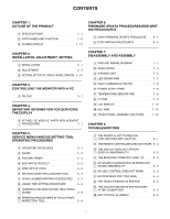
CONTENTS
Parts marked with "
!
" are important for maintaining the safety of the set. Be sure to replace these parts with specified
ones for maintaining the safety and performance of the set.
This document has been published to be used
for after sales service only.
The contents are subject to change without notice.
PNT321SME2
LCD MONITOR/
TOUCH-PANEL-
INTEGRATED DISPLAY
PN-T321
MODEL
PN-T322B
■
LEAD-FREE SOLDER
CHAPTER 1.
OUTLINE OF THE PRODUCT . . . . . . . . . . . . . . . . . 1 - 1
CHAPTER 2.
INSTALLATION, ADJUSTMENT, SETTING. . . . . . . 2 - 1
CHAPTER 3.
CONTROLLING THE MONITOR WITH A PC . . . . .3 - 1
CHAPTER 4.
IMPORTANT INFORMATION FOR SERVICING
THE DISPLAY . . . . . . . . . . . . . . . . . . . . . . . . . . . . .4 - 1
CHAPTER 5.
SERVICE MENU/VARIOUS SETTING TOOL
OPERATING PROCEDURES . . . . . . . . . . . . . . . . .5 - 1
CHAPTER 6.
FIRMWARE UPDATA PROCEDURES/EDID
WRITING PROCEDURES . . . . . . . . . . . . . . . . . . . .6 - 1
CHAPTER 7.
DISASSEMBLY AND ASSEMBLY . . . . . . . . . . . . . . 7 - 1
CHAPTER 8.
TROUBLESHOOTING . . . . . . . . . . . . . . . . . . . . . . . 8 - 1
CHAPTER 9.
HARDWARE DESCRIPTIONS. . . . . . . . . . . . . . . . .9 - 1