Sharp PN-T322B Service Manual - Page 64
Unscrew 4pcs of screw, x 10 black, and remove 3 bezels
 |
View all Sharp PN-T322B manuals
Add to My Manuals
Save this manual to your list of manuals |
Page 64 highlights
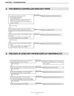
CHAPTER 7. DISASSEMBLY AND ASSEMBLY ■ PN-T322B 1 ) Remove the FFC together with the fixing tape from the LCD module. Unscrew 2pcs of screw A (4 x 10 (black)). Unscrew 4pcs of screw B (4 x 6 (black)), and then remove the plate. Unscrew 4pcs of screw C (4 x 10 (black)), and remove 3 bezels, and remove the LCD module from the Front Cabinet. Slide in the arrow direction of the engraved mark to remove. Bezel x 3 CAUTION SCREW TIGHTENING TORQUE n Screw A, C: 0.7 - 0.9N•m n Screw B: 0.5 - 0.6N•m Plate Fixing tape x 5 Key FFC Screw B x 4 Screw A x 2 Screw C x 4 PN-T321/T322B DISASSEMBLY AND ASSEMBLY 7 - 14
-
 1
1 -
2
-
3
-
4
-
5
-
6
-
7
-
8
-
9
-
10
-
11
-
12
-
13
-
14
-
15
-
16
-
17
-
18
-
19
-
20
-
21
-
22
-
23
-
24
-
25
-
26
-
27
-
28
-
29
-
30
-
31
-
32
-
33
-
34
-
35
-
36
-
37
-
38
-
39
-
40
-
41
-
42
-
43
-
44
-
45
-
46
-
47
-
48
-
49
-
50
-
51
-
52
-
53
-
54
-
55
-
56
-
57
-
58
-
 59
59 -
 60
60 -
 61
61 -
 62
62 -
 63
63 -
 64
64 -
 65
65 -
 66
66 -
 67
67 -
 68
68 -
 69
69 -
70
-
71
-
72
-
73
-
74
-
75
-
76
-
77
-
78
-
79
-
80
 |
 |

CHAPTER 7.
DISASSEMBLY AND ASSEMBLY
PN-T321/T322B
DISASSEMBLY AND ASSEMBLY
7 – 14
■
PN-T322B
1 )
Remove the FFC together with the fixing tape from the LCD module. Unscrew 2pcs of screw
A
(4 x 10 (black)). Unscrew 4pcs of screw
B
(4 x 6
(black)), and then remove the plate.
Unscrew 4pcs of screw
C
(4 x 10 (black)), and remove 3 bezels, and remove the LCD module from the Front Cabinet.
CAUTION
SCREW TIGHTENING TORQUE
n
Screw
A
,
C
: 0.7 - 0.9N•m
n
Screw
B
: 0.5 - 0.6N•m
Screw
x 4
B
Screw
x 2
A
Screw
x 4
C
Slide in the arrow direction of
the engraved mark to remove.
Plate
Key FFC
Bezel x 3
Fixing tape x 5