Sharp PN-T322B Service Manual - Page 79
Basic Structure, Touch Panel Unit, Controller Pwb
 |
View all Sharp PN-T322B manuals
Add to My Manuals
Save this manual to your list of manuals |
Page 79 highlights
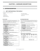
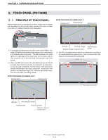
CHAPTER 9. HARDWARE DESCRIPTIONS 5 - 2. BASIC STRUCTURE 2 1 The touch panel unit is composed in the structure below. Since the cor- 3 rection information of the camera unit is written in the controller PWB, it 4 7 must be used in a pair. (Setting in 1 to 1.) In servicing, therefore, the touch panel unit must be replaced as needed. If the unit is not replaced in a pair, calibration is not performed 8 properly, generating a shift in the detected position. 5 Number of the Controller PWB side 6 9 Number of the Camera unit side ■ TOUCH PANEL UNIT No. Name 1 USB cable 2 Controller PWB 3 FFC 4 Camera unit 1 5 Emitted & Reflected IR light 6 Glass substrate 7 Camera unit 2 8 Camera field of view 9 Retroreflective border 3 ■ CONTROLLER PWB 1 Provided at the back of the LCD module. 2 4 6 7 1 2 3 5 No. Name 1 Camera 1 interface connector 2 Camera 2 interface connector 3 USB interface connector No. Name 1 Controller PWB 2 Camera unit 1 3 Camera unit 2 4 Retroreflective border (left side) 5 Retroreflective border (right side) 6 Glass substrate 7 Retroreflective border (Lower side) PN-T321/T322B HARDWARE DESCRIPTIONS 9 - 6
-
 1
1 -
2
-
3
-
4
-
5
-
6
-
7
-
8
-
9
-
10
-
11
-
12
-
13
-
14
-
15
-
16
-
17
-
18
-
19
-
20
-
21
-
22
-
23
-
24
-
25
-
26
-
27
-
28
-
29
-
30
-
31
-
32
-
33
-
34
-
35
-
36
-
37
-
38
-
39
-
40
-
41
-
42
-
43
-
44
-
45
-
46
-
47
-
48
-
49
-
50
-
51
-
52
-
53
-
54
-
55
-
56
-
57
-
58
-
59
-
60
-
61
-
62
-
63
-
64
-
65
-
66
-
67
-
68
-
69
-
70
-
71
-
72
-
73
-
 74
74 -
 75
75 -
 76
76 -
 77
77 -
 78
78 -
 79
79 -
 80
80
 |
 |
