Sharp PN-T322B Service Manual - Page 6
Dimensional Drawings
 |
View all Sharp PN-T322B manuals
Add to My Manuals
Save this manual to your list of manuals |
Page 6 highlights
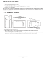
CHAPTER 1. OUTLINE OF THE PRODUCT *1 Uses the provided conversion cable (for AV video). *2 Uses the provided conversion cable (for AV component). *3 Temperature condition may change when using the display together with the optional equipments recommended by SHARP. In such cases, please check the temperature condition specified by the optional equipments. *4 D-SUB input (factory default setting) As a part of our policy of continuous improvement, SHARP reserves the right to make design and specification changes for product improvement without prior notice. The performance specification figures indicated are nominal values of production units. There may be some deviations from these values in individual units. 1 - 2. DIMENSIONAL DRAWINGS PN-T322B 2-7/16 [62] 1-1/2 [38] PN-T321 1-15/16 [49.1] 1 [25.3] 18-13/16 [478] 30-1/4 [769] Opening width (27-5/8 [701]) VESA holes *1 7-7/8 [200] 18-1/8 [461] Opening height (15-9/16 [396]) 7-7/8 [200] Unit: inch [mm] * Note that the values shown are approximate values. *1 When mounting the monitor, be sure to use a wall-mount bracket that complies with the VESA-compatible mounting method. SHARP recommends using M6 screws and tighten the screws. Note that screw hole depth of the monitor is 3/8 inch (10mm). Loose mounting may cause the product to fall, resulting in serious personal injuries as well as damage to the product. The screw and hole should come together with over 5/16 inch (8mm) length of thread. Use a bracket which has been approved for UL1678 standard, and which can endure at least 4 times or more the weight of the monitor. PN-T321/T322B OUTLINE OF THE PRODUCT 1 - 2
-
 1
1 -
 2
2 -
 3
3 -
 4
4 -
 5
5 -
 6
6 -
 7
7 -
 8
8 -
 9
9 -
 10
10 -
 11
11 -
 12
12 -
13
-
14
-
15
-
16
-
17
-
18
-
19
-
20
-
21
-
22
-
23
-
24
-
25
-
26
-
27
-
28
-
29
-
30
-
31
-
32
-
33
-
34
-
35
-
36
-
37
-
38
-
39
-
40
-
41
-
42
-
43
-
44
-
45
-
46
-
47
-
48
-
49
-
50
-
51
-
52
-
53
-
54
-
55
-
56
-
57
-
58
-
59
-
60
-
61
-
62
-
63
-
64
-
65
-
66
-
67
-
68
-
69
-
70
-
71
-
72
-
73
-
74
-
75
-
76
-
77
-
78
-
79
-
80
 |
 |
