Sharp PN-T322B Service Manual - Page 32
Important Information For Servicing The Display, 1. I/f Pwb, Lcd Module
 |
View all Sharp PN-T322B manuals
Add to My Manuals
Save this manual to your list of manuals |
Page 32 highlights
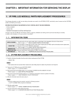
CHAPTER 4. IMPORTANT INFORMATION FOR SERVICING THE DISPLAY 1. I/F PWB, LCD MODULE, PARTS REPLACEMENT PROCEDURES The following information as well as user setting information are saved to the EEPROM (IC1007) controlled by main firmware and the EEPROM (IC401) controlled by sub firmware. INFORMATION STORED IN THE EEPROM'S (IC1007) CONTROLLED BY THE MAIN FIRMWARE. n SERIAL NUMBER n USAGE TIME n TEMPERATURE MONITOR SETTING INFORMATION Therefore, when the I/F PWB, the LCD module, IC1007 is replaced, initialization and setting must be performed according to necessity. In addition, after completion of the work, perform "ALL RESET". 1 - 1. INFORMATION ITEMS SERIAL NUMBER USAGE TIME TEMPERATURE MONITOR SETTING INFORMATION The machine has its own serial number which is described on the nameplate at the back of the machine. 3Refer to page 5 - 4 "7. SERIAL NUMBER WRITING PROCEDURES". This information is linked with the LCD module. When replacing the I/F PWB, read the information before replacement, and write it to the new I/F PWB after replacement. 3Refer to page 5 - 5 "8. USAGE TIME SETTING PROCEDURE". This is the setting information related to temperature watch. Execute resetting when replacing the I/F PWB or the LCD module. 3Refer to page 5 - 6 "9. TEMPERATURE MONITOR SETTING PROCEDURES". 1 - 2. I/F PWB REPLACEMENT PROCEDURES 1 ) Read the following information from the monitor before replacement of the I/F PWB. n USAGE TIME MEMO n If the machine does not operate before replacement and reading cannot be made, this procedure is not required. 2 ) Replace the I/F PWB and execute FACTORY RESET. 3Refer to page 5 - 2 "3. FACTORY RESET". 3 ) Each service part has the EDID written in it. If necessary, the EDID should be updated to the latest. 3Refer to page 6 - 2 "2. EDID WRITING PROCEDURES". 4 ) Each service part has the firmware written in it. If necessary, the firmware should be updated to the latest. 3Refer to page 6 - 1 "1. MAIN FIRMWARE UPDATE PROCEDURE". 5 ) Write the information read in the above step 1). MEMO n When the reading cannot be executed, conduct the following operation. --- Set "0" to USAGE TIME and perform initialization. 6 ) Write the serial number. 3Refer to page 5 - 4 "7. SERIAL NUMBER WRITING PROCEDURES". 7 ) Reset the temperature watch setting information. 3Refer to page 5 - 6 "9. TEMPERATURE MONITOR SETTING PROCEDURES". PN-T321/T322B IMPORTANT INFORMATION FOR SERVICING THE DISPLAY 4 - 1
-
 1
1 -
2
-
3
-
4
-
5
-
6
-
7
-
8
-
9
-
10
-
11
-
12
-
13
-
14
-
15
-
16
-
17
-
18
-
19
-
20
-
21
-
22
-
23
-
24
-
25
-
26
-
 27
27 -
 28
28 -
 29
29 -
 30
30 -
 31
31 -
 32
32 -
 33
33 -
 34
34 -
 35
35 -
 36
36 -
 37
37 -
38
-
39
-
40
-
41
-
42
-
43
-
44
-
45
-
46
-
47
-
48
-
49
-
50
-
51
-
52
-
53
-
54
-
55
-
56
-
57
-
58
-
59
-
60
-
61
-
62
-
63
-
64
-
65
-
66
-
67
-
68
-
69
-
70
-
71
-
72
-
73
-
74
-
75
-
76
-
77
-
78
-
79
-
80
 |
 |
