Sharp PN-T322B Service Manual - Page 75
Power Supply Pwb Unit, Temperature Sensor Board Unit, <temperature Monitoring Function>
 |
View all Sharp PN-T322B manuals
Add to My Manuals
Save this manual to your list of manuals |
Page 75 highlights
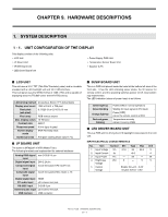
CHAPTER 9. HARDWARE DESCRIPTIONS OUTPUT ELECTRICAL CHARACTERISTICS Item Output Current (Max) Output Current (Min) Output Voltage Output power of total Output Ripple/ Noise Efficiency Symbol Test Conditions Iout Vin=24V; Von=5V; Vbrit=0V Iout Vin=24V; Von=5V; Vbrit=5V Vout Vin=24V; Von=5V; Vbrit=0V Vig1 Vin=24V; Von=5V; Vbrit=0V; 25°C Vp-p Vin=24V; Von=5V; Vbrit=0V η Vin=24V; Von=5V; Vbrit=0V; Min Type Max Unit --- 600 --- mA mA 20.3 --- 25.2 Vrms --- 50 --- W --- 200 --- mV 80 --- --- % .PIN ASSIGNMENTS Pin Symbol Description No. Parameter Input 1, 2 connector: J7 5, 6 Vin Supply voltage Gnd Ground 21.6 - 26.4V 0V 4 DIM Dimming 5V=Brightness Max control 0V=Brightness Min 3 EN Standby/ Von=2.5 - 5.0V operation Voff=0 - 0.6V Output 1, 2 connector: 3 J1, J2 LED- Low voltage 0Vrms LED+ High voltage 23Vrms Output 1 connector: 2 J3, J4 LED- Low voltage 0Vrms LED+ High voltage 23Vrms ■ POWER SUPPLY PWB UNIT OUTPUT ELECTRICAL CHARACTERISTICS Output voltage, Load Current & Load Regulation Output voltage +V1 (+24V) +V2 (+12V) +V3 (+5V) +V4 (+5VSB) Load Regulation ±10% ±10% ±5% ±5% Min Load 0.1A 0.1A 0.1A 50mA Rate Load 3.5A 0.1 - 1.0A 0.1 - 1.5A 0.5A Max current * 5.0A 2.0A 2.5A 1.0A * The peak current should be test at other of dc output at rate current, and the peak current pulse width within 100ms. TERMINAL ASSIGNMENT AND FUNCTION CN1 (PIN: 3.96mm) CON2 (PIN: 2.54mm) CON3 (PIN: 2.54mm) CON1 (PIN: 2.54mm) Terminal PIN1 PIN2 PIN3 PIN1, 2 PIN3, 4 PIN1, 2, 3, 4 PIN5, 6, 7, 8 PIN12, 13 PIN1, 2, 9, 10, 11 PIN6 PIN3, 4, 7, 8 PIN5 Function AC-L NC AC-N +24V GND +24V GND +12V GND +5VSB +5V ON/OFF ■ TEMPERATURE SENSOR BOARD UNIT This temperature sensor board unit monitors the temperature inside the display during operation. When the ambient temperature in use exceeds the guaranteed operating temperature, the brightness goes down automatically to restrain the increase of temperature. However, this is a temporary remedial measure and not a guaranteed use, so you need to get rid of the root cause promptly. Also, it can provide notification when the ambient temperature in use goes beyond the guaranteed operating temperature by LED indication (red-green blinking) or OSD message ("Monitor Temperature"). Set the "Temperature Anomaly Indication" of "Special Functions" as follows. n When it is set to "OSD&LED", the notification is given by LED and OSD message. n When it is set to "LED", the notification is given by LED. (Factory default) n When it is set to "OFF", no notification is provided. If the temperature is increasing further, the display goes into standby mode. In this case, the LED inevitably blinks in red and green. The description of abnormal temperature can be obtained through RS232C. PN-T321/T322B HARDWARE DESCRIPTIONS 9 - 2
-
 1
1 -
2
-
3
-
4
-
5
-
6
-
7
-
8
-
9
-
10
-
11
-
12
-
13
-
14
-
15
-
16
-
17
-
18
-
19
-
20
-
21
-
22
-
23
-
24
-
25
-
26
-
27
-
28
-
29
-
30
-
31
-
32
-
33
-
34
-
35
-
36
-
37
-
38
-
39
-
40
-
41
-
42
-
43
-
44
-
45
-
46
-
47
-
48
-
49
-
50
-
51
-
52
-
53
-
54
-
55
-
56
-
57
-
58
-
59
-
60
-
61
-
62
-
63
-
64
-
65
-
66
-
67
-
68
-
69
-
 70
70 -
 71
71 -
 72
72 -
 73
73 -
 74
74 -
 75
75 -
 76
76 -
 77
77 -
 78
78 -
 79
79 -
 80
80
 |
 |
