Sharp PN-T322B Service Manual - Page 67
POWER SUPPLY PWB., When assembling
 |
View all Sharp PN-T322B manuals
Add to My Manuals
Save this manual to your list of manuals |
Page 67 highlights
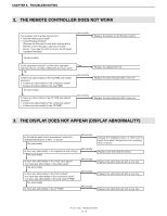
CHAPTER 7. DISASSEMBLY AND ASSEMBLY 5 ) Remove six screws A (4 x 8, silver), and remove four angles. Remove two fixing tapes of the FFC from the upper side of the machine, and remove the touch panel assembly. 3Refer to page 7 - 8 "6. POWER SUPPLY PWB". Fixing tape x 2 Angle(Top side) Angle(Lower side) Touch panel assembly Screw A x 6 CAUTION NOTE FOR ASSEMBLY n When assembling, first attach the angle (lower side) and then attach the touch panel assembly, and slide the angle (upper side) in the arrow direction to attach. In addition, do not stretch the FFC cable but allow slack and attach the fixing tape to the FFC. SCREW TIGHTENING TORQUE n 0.7 - 0.9N•m PN-T321/T322B DISASSEMBLY AND ASSEMBLY 7 - 17
-
 1
1 -
2
-
3
-
4
-
5
-
6
-
7
-
8
-
9
-
10
-
11
-
12
-
13
-
14
-
15
-
16
-
17
-
18
-
19
-
20
-
21
-
22
-
23
-
24
-
25
-
26
-
27
-
28
-
29
-
30
-
31
-
32
-
33
-
34
-
35
-
36
-
37
-
38
-
39
-
40
-
41
-
42
-
43
-
44
-
45
-
46
-
47
-
48
-
49
-
50
-
51
-
52
-
53
-
54
-
55
-
56
-
57
-
58
-
59
-
60
-
61
-
 62
62 -
 63
63 -
 64
64 -
 65
65 -
 66
66 -
 67
67 -
 68
68 -
 69
69 -
 70
70 -
 71
71 -
 72
72 -
73
-
74
-
75
-
76
-
77
-
78
-
79
-
80
 |
 |

CHAPTER 7.
DISASSEMBLY AND ASSEMBLY
PN-T321/T322B
DISASSEMBLY AND ASSEMBLY
7 – 17
5 )
Remove six screws
A
(4 x 8, silver), and remove four angles. Remove two fixing tapes of the FFC from the upper side of the machine, and
remove the touch panel assembly.
3
Refer to page 7 - 8
"6. POWER SUPPLY PWB".
CAUTION
NOTE FOR ASSEMBLY
n
When assembling, first attach the angle (lower side) and then attach the touch panel assembly, and slide the angle (upper side) in the arrow
direction to attach.
In addition, do not stretch the FFC cable but allow slack and attach the fixing tape to the FFC.
SCREW TIGHTENING TORQUE
n
0.7 - 0.9N•m
Fixing tape x 2
Angle(Top side)
Angle(Lower side)
Touch panel assembly
A
Screw
x 6