Sony VPL CX85 Operating Instructions - Page 14
Connector Panel, INPUT key, TILT adjustment key, MENU key, ENTER/Arrow, Indicators - lamp life
 |
UPC - 027242644274
View all Sony VPL CX85 manuals
Add to My Manuals
Save this manual to your list of manuals |
Page 14 highlights
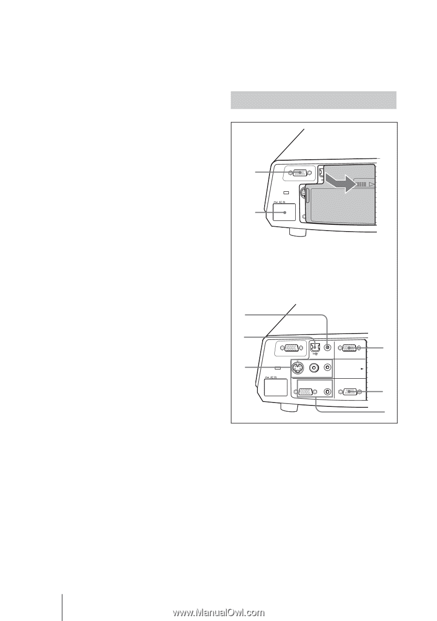
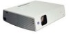
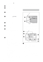
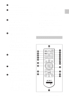
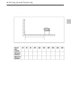
For details on the I/1 indicators, see page 25. 3 INPUT key 4 TILT adjustment key For details, see "Projecting" on page 23. 5 MENU key Displays the on-screen menu. Press again to clear the menu. 6 ENTER/Arrow(f/F/g/G) keys Enter the settings of items in the menu system. Select the menu or make various adjustments. 7 FOCUS +/- keys Adjusts the picture focus. 8 ZOOM +/- keys Adjusts the picture size. 9 SIDE SHOT +/- key Adjusts the horizontal trapezoidal distortion/H keystone correction of the picture. For details, see "Side Shot" on page 39 and ""Side Shot" and "V Keystone" Adjustments" on page 60. q; Indicators • POWER SAVING Lights when the projector is in power saving mode. • TEMP (Temperature)/FAN Lights or flashes under the following conditions: - Lights when the temperature inside the projector becomes unusually high. - Flashes when the fan is broken. For details on the TEMP/FAN indicator, see page 47. • LAMP/COVER Lights or flashes under the following conditions: - Lights when the lamp has reached the end of its life or reaches a high temperature. 14 GB Location and Function of Controls - Flashes when the lamp cover or air filter cover is not secured firmly. For details on the LAMP/COVER and TEMP/FAN indicator, see page 47. Connector Panel 1 2 INPUT A AUDIO VIDEO IN INPUPSUHTSBLIDE S VIDEO VIDEO AUDIO OUTPUT MONITOR AUDIO REMOTE RS-232C Open the cover when using the INPUT B or VIDEO IN connector. To open the cover, push the cover and slide it toward the right until it locks. To close the cover, press the cover to unlock it and slide the cover toward the left. 3 4 5 INPUT A AUDIO INPUT A/B VIDEO IN S VIDEO VIDEO AUDIO OUTPUT MONITOR AUDIO INPUT B COVER LOCK/UNLOCK REMOTE RS-232C 6 7 8 1 INPUT A connector (HD D-sub 15-pin, female) Inputs a computer signal, video GBR signal, component signal, or DTV signal depending on equipment to be connected. Connects to the output connector of equipment using the supplied cable or an optional cable. For details, see "Connecting with a Computer" on page 20 and "Connecting with a VCR" on page 22.
-
 1
1 -
2
-
3
-
4
-
5
-
6
-
7
-
8
-
 9
9 -
 10
10 -
 11
11 -
 12
12 -
 13
13 -
 14
14 -
 15
15 -
 16
16 -
 17
17 -
 18
18 -
 19
19 -
20
-
21
-
22
-
23
-
24
-
25
-
26
-
27
-
28
-
29
-
30
-
31
-
32
-
33
-
34
-
35
-
36
-
37
-
38
-
39
-
40
-
41
-
42
-
43
-
44
-
45
-
46
-
47
-
48
-
49
-
50
-
51
-
52
-
53
-
54
-
55
-
56
-
57
-
58
-
59
-
60
-
61
-
62
-
63
-
64
-
65
-
66
-
67
-
68
-
69
-
70
-
71
-
72
-
73
-
74
-
75
-
76
-
77
-
78
-
79
-
80
-
81
-
82
-
83
-
84
-
85
-
86
-
87
-
88
-
89
-
90
-
91
-
92
-
93
-
94
-
95
-
96
-
97
-
98
-
99
-
100
-
101
-
102
-
103
-
104
-
105
-
106
-
107
-
108
-
109
-
110
-
111
-
112
-
113
-
114
-
115
-
116
-
117
-
118
-
119
-
120
-
121
-
122
-
123
-
124
-
125
-
126
-
127
-
128
-
129
-
130
-
131
-
132
-
133
-
134
-
135
-
136
-
137
-
138
-
139
-
140
-
141
-
142
-
143
-
144
-
145
-
146
-
147
-
148
-
149
-
150
-
151
-
152
-
153
-
154
-
155
-
156
-
157
-
158
-
159
-
160
-
161
-
162
-
163
-
164
-
165
-
166
-
167
-
168
-
169
-
170
-
171
-
172
-
173
-
174
-
175
-
176
-
177
-
178
-
179
-
180
-
181
-
182
-
183
-
184
-
185
-
186
-
187
-
188
-
189
-
190
-
191
-
192
 |
 |