Sony VPL CX85 Operating Instructions - Page 15
Remote Commander, INPUT B connector HD D-sub
 |
UPC - 027242644274
View all Sony VPL CX85 manuals
Add to My Manuals
Save this manual to your list of manuals |
Page 15 highlights
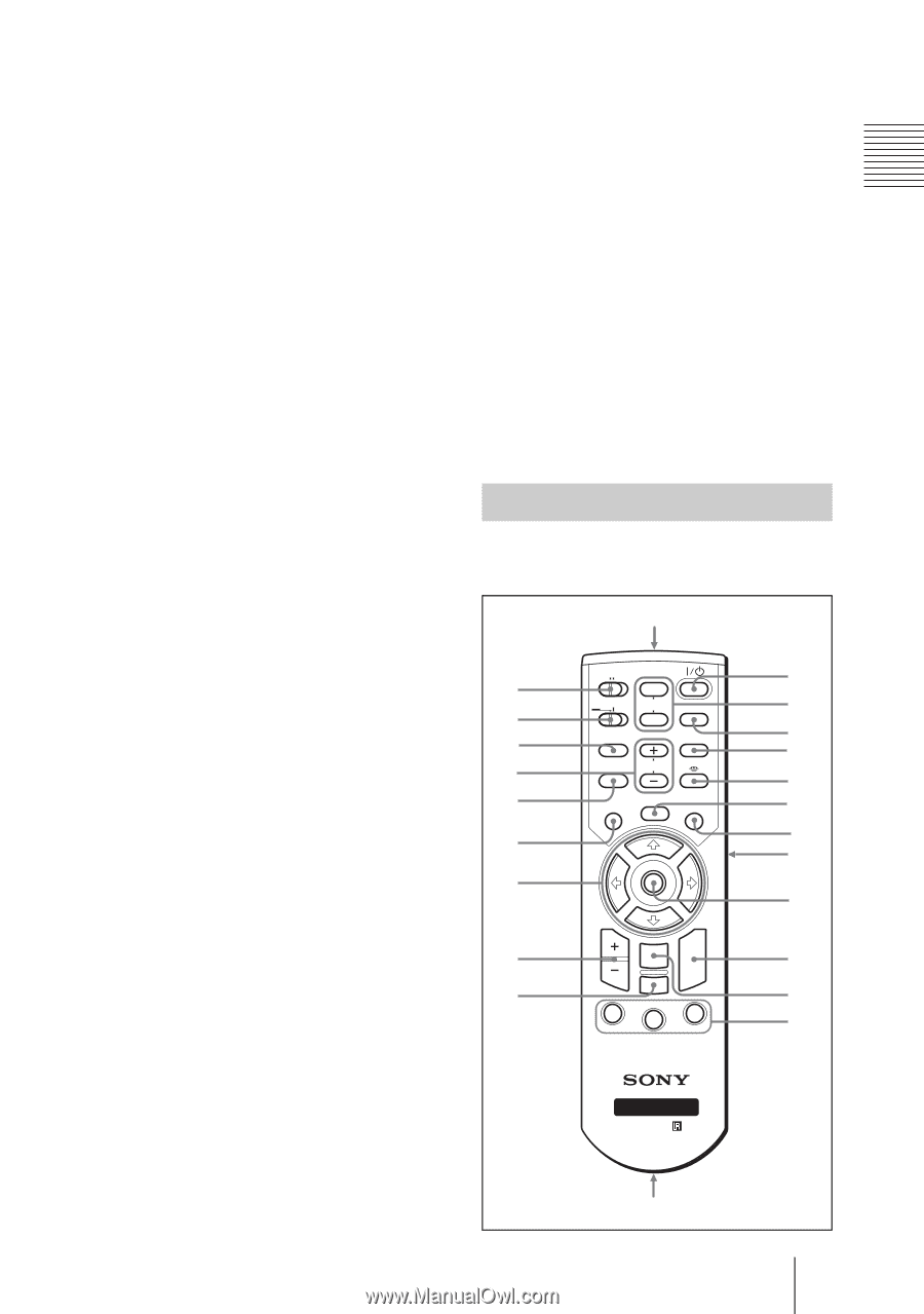
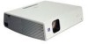
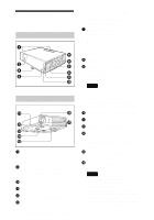
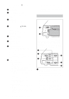
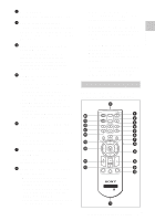
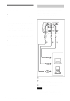
2 AC IN socket Connects the supplied AC power cord. 3 AUDIO (stereo minijack) connector (common INPUT A/B) When listening to sound output from the computer, connect to the audio output of the computer. 4 USB connector (USB plug for upstream, 4-pin) Connect to the USB connector of a computer. When you connect the projector to the computer, you can control the mouse function with the supplied Remote Commander. 5 VIDEO IN (Video input) connector Connect to external video equipment such as a VCR. • S VIDEO (mini DIN 4-pin): Connects to the S video output (Y/C video output) of video equipment. • VIDEO (phono type): Connects to the composite video output of video equipment. • AUDIO (stereo minijack): Connects to the audio output of the VCR. 6 INPUT B connector (HD D-sub 15-pin, female) Connect to external equipment such as a computer. Connects to the monitor output of a computer using an optional cable. 7 RS-232C connector (D-sub 9pin, female) Connects to a computer to operate the projector from the computer. 8 OUTPUT connector (HD D-sub 15-pin, female) • MONITOR: Connect to the video input connector of the monitor. Outputs signals from the selected channel and computer signals only from among the signals from the INPUT A or INPUT B. • AUDIO (stereo minijack): Connects to external active speakers. The volume of the speakers can be controlled by the VOLUME+/- keys on the Remote Commander. When INPUT A or B is selected, the sound input to the AUDIO connector which is common for INPUT A/B is output. When the Memory Stick is selected in INPUT C, the sound saved in the Memory Stick is output. When "Air Shot" is selected, no sound is output. When VIDEO or S VIDEO is selected, the sound input to the AUDIO input connector of VIDEO IN is output. Remote Commander The keys that have the same names as those on the control panel function identically. wa w; ql qk qj qh qg qf COMMAND OFF ON PIC PJ NETWORK MUTING AUDIO INPUT LENS APA TILT/KEYSTONE VOLUME MENU/ TAB AIR SHOT FREEZE 1 2 3 4 5 6 7 8a 8b qd qs ENTER R CLICK D ZOOM RESET/ ESCAPE 1 3 2 FUNCTION RM-PJM15 PROJECTOR RM-PJM17 8c 9 q; qa 15 Location and Function of Controls GB Overview
-
 1
1 -
2
-
3
-
4
-
5
-
6
-
7
-
8
-
9
-
 10
10 -
 11
11 -
 12
12 -
 13
13 -
 14
14 -
 15
15 -
 16
16 -
 17
17 -
 18
18 -
 19
19 -
 20
20 -
21
-
22
-
23
-
24
-
25
-
26
-
27
-
28
-
29
-
30
-
31
-
32
-
33
-
34
-
35
-
36
-
37
-
38
-
39
-
40
-
41
-
42
-
43
-
44
-
45
-
46
-
47
-
48
-
49
-
50
-
51
-
52
-
53
-
54
-
55
-
56
-
57
-
58
-
59
-
60
-
61
-
62
-
63
-
64
-
65
-
66
-
67
-
68
-
69
-
70
-
71
-
72
-
73
-
74
-
75
-
76
-
77
-
78
-
79
-
80
-
81
-
82
-
83
-
84
-
85
-
86
-
87
-
88
-
89
-
90
-
91
-
92
-
93
-
94
-
95
-
96
-
97
-
98
-
99
-
100
-
101
-
102
-
103
-
104
-
105
-
106
-
107
-
108
-
109
-
110
-
111
-
112
-
113
-
114
-
115
-
116
-
117
-
118
-
119
-
120
-
121
-
122
-
123
-
124
-
125
-
126
-
127
-
128
-
129
-
130
-
131
-
132
-
133
-
134
-
135
-
136
-
137
-
138
-
139
-
140
-
141
-
142
-
143
-
144
-
145
-
146
-
147
-
148
-
149
-
150
-
151
-
152
-
153
-
154
-
155
-
156
-
157
-
158
-
159
-
160
-
161
-
162
-
163
-
164
-
165
-
166
-
167
-
168
-
169
-
170
-
171
-
172
-
173
-
174
-
175
-
176
-
177
-
178
-
179
-
180
-
181
-
182
-
183
-
184
-
185
-
186
-
187
-
188
-
189
-
190
-
191
-
192
 |
 |