Yamaha YSP 4000 Owner's Manual - Page 32
Connecting other external components - support
 |
UPC - 027108928760
View all Yamaha YSP 4000 manuals
Add to My Manuals
Save this manual to your list of manuals |
Page 32 highlights
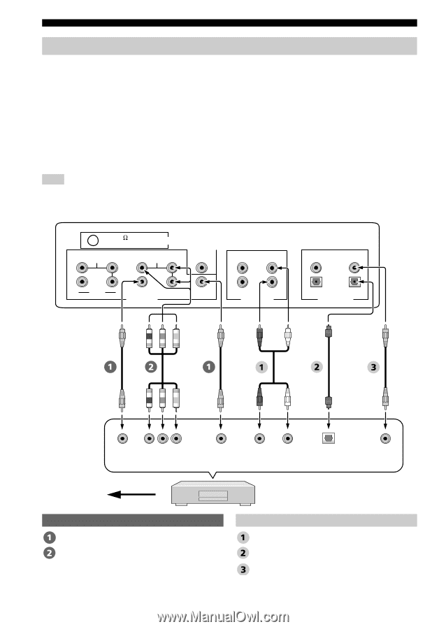
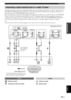
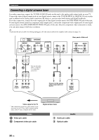
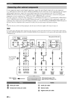
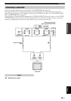
Connections Connecting other external components If your component supports optical digital connections, connect the optical digital output jack on your component (e.g., DVD player/recorder) to the AUX 1 OPTICAL DIGITAL IN jack on this unit. If your component does not support optical digital connections, connect the coaxial digital output jack on your component to the AUX 2 COAXIAL DIGITAL IN jack on this unit. If your component does not support any digital connections, connect the analog audio output jacks on your component (e.g., VCR) to the AUX 1 AUDIO IN jacks on this unit. For video connection, connect the video output jack of your DVD player/recorder, etc. to the DVD/AUX 2 VIDEO IN (or AUX 1 VIDEO IN) jack of this unit. If your DVD player/recorder, etc. has component video output jacks, connect the component video output jacks of your DVD player/recorder, etc. to the DVD/AUX 2 COMPONENT VIDEO IN jacks of this unit. Once the component video connection is made, you can enjoy images with better resolution. y To prevent the optical cable from being unplugged, affix the optical cable in the supplied cable clamp (see page 21). Note If you make analog and digital audio connections at the same time as shown in the illustration below, the digital audio signals input at the AUX 1 OPTICAL DIGITAL IN or AUX 2 COAXIAL DIGITAL IN jack take priority over the analog audio signals input at the AUX 1 AUDIO IN jacks. FM75 UNBAL. ANTENNA COMPONENT COMPONENT SUBWOOFER STB DVD/AUX 2 VIDEO IN AUX 1 TV/STB AUX 1 AUDIO IN Rear panel of this unit DVD AUX 2 COAXIAL OPTICAL TV/STB AUX 1 DIGITAL IN * You can only make either a composite * * or a component connection. Video output Component video output Video signal to the TV Video Video pin cable Component video pin cable Video output R L Analog audio output Optical digital output Coaxial digital output DVD player/recorder, VCR, game console, CD player, etc. Audio Audio pin cable Optical cable Digital audio pin cable 28 En
-
 1
1 -
2
-
3
-
4
-
5
-
6
-
7
-
8
-
9
-
10
-
11
-
12
-
13
-
14
-
15
-
16
-
17
-
18
-
19
-
20
-
21
-
22
-
23
-
24
-
25
-
26
-
 27
27 -
 28
28 -
 29
29 -
 30
30 -
 31
31 -
 32
32 -
 33
33 -
 34
34 -
 35
35 -
 36
36 -
 37
37 -
38
-
39
-
40
-
41
-
42
-
43
-
44
-
45
-
46
-
47
-
48
-
49
-
50
-
51
-
52
-
53
-
54
-
55
-
56
-
57
-
58
-
59
-
60
-
61
-
62
-
63
-
64
-
65
-
66
-
67
-
68
-
69
-
70
-
71
-
72
-
73
-
74
-
75
-
76
-
77
-
78
-
79
-
80
-
81
-
82
-
83
-
84
-
85
-
86
-
87
-
88
-
89
-
90
-
91
-
92
-
93
-
94
-
95
-
96
-
97
-
98
-
99
-
100
-
101
-
102
-
103
-
104
-
105
-
106
-
107
-
108
-
109
-
110
-
111
-
112
-
113
-
114
-
115
-
116
-
117
-
118
-
119
-
120
-
121
-
122
-
123
-
124
-
125
-
126
-
127
-
128
-
129
-
130
-
131
-
132
-
133
-
134
-
135
-
136
-
137
 |
 |