Yamaha YSP 4000 Owner's Manual - Page 84
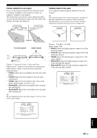
Ahorizontal Angle 1/5, Bvertical Angle 1/5, Cbeam Travel Length, Horizontal Angle Horizontal Angle
 |
UPC - 027108928760
View all Yamaha YSP 4000 manuals
Add to My Manuals
Save this manual to your list of manuals |
Page 84 highlights
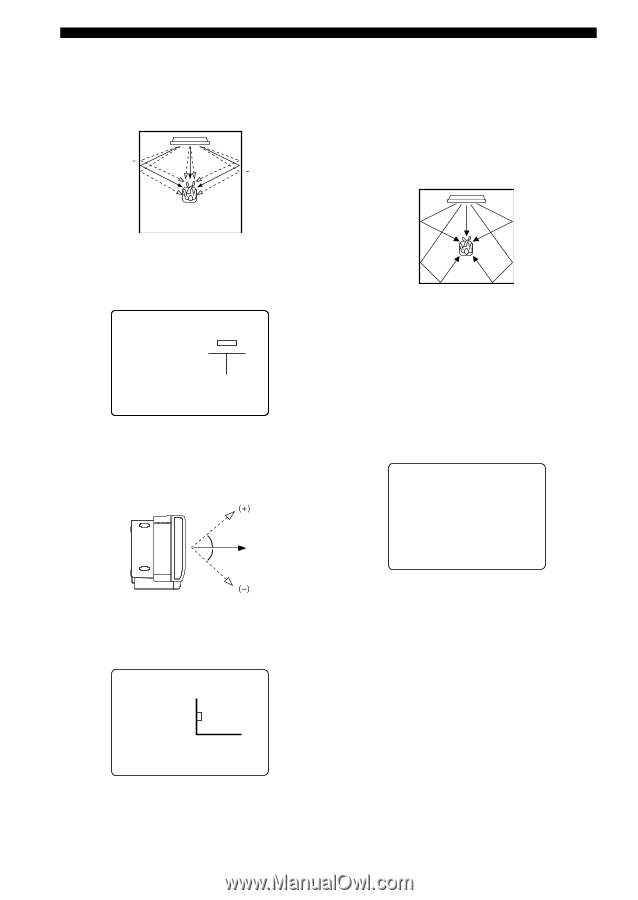
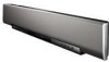
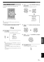
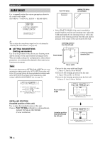
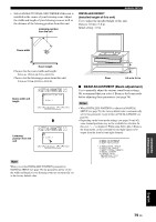
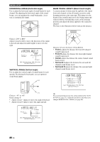
MANUAL SETUP HORIZONTAL ANGLE (Horizontal angle) Use to adjust the horizontal angle of sound beams for each channel. By adjusting the horizontal angle of the sound beams, you can optimize the sound beam paths. A test tone is automatically output. () (+) (+) () BEAM TRAVEL LENGTH (Beam travel length) A certain amount of delay must be applied to the sound from each channel so that all sounds can arrive at the listening position at the same time. This menu sets the distance that sound beams travel after being output and reflected off the wall until they arrive at the listening position and adjusts the delay applied to the respective channel. The lines in the illustration below indicate the distance. p p p Choices: L90° to R90° Adjust toward L (left) to move the direction of the output to the left and adjust toward R (right) to move it to the right. a)HORIZONTAL ANGLE 1/5 5 beam Front L L90 R90 L65deg * 0(deg) p [ ]/[ ]:Up/Down [ ]/[ ]:Sel [ENTER]:Return p p VERTICAL ANGLE (Vertical angle) Use to adjust the vertical angle of sound beams for each speaker. By altering the beam path, you can optimize sound beam angles. p p Choices: 0.3 m to 24.0 m (1.0 ft to 80.0 ft) • Front L adjusts the distance the front left channel sound beams travel. • Front R adjusts the distance the front right channel sound beams travel. • Center adjusts the distance the center channel sound beams travel. • Surround L adjusts the distance the surround left channel sound beams travel. • Surround R adjusts the distance the surround right channel sound beams travel. c)BEAM TRAVEL LENGTH 5 beam . Front L;;;;;;;6.0m Front R;;;;;;;6.0m Center;;;;;;;;2.5m Surround L;;;;9.1m Surround R;;;;9.1m p [ ]/[ ]:Up/Down [ ]/[ ]:Sel [ENTER]:Return Choices: -45° to +45° Initial setting: 0° • Adjust toward - (minus) to move the angle downward. • Adjust toward + (plus) to move the angle upward. y We recommend that you use the setting optimized by AUTO SETUP (see page 37). Adjust this parameter only when you changed HORIZONTAL ANGLE (see page 80). b)VERTICAL ANGLE 1/5 5 beam Front L 0deg. (+) ------0deg. (-) p p p [ ]/[ ]:Up/Down [ ]/[ ]:Sel [ENTER]:Return 80 En
-
 1
1 -
2
-
3
-
4
-
5
-
6
-
7
-
8
-
9
-
10
-
11
-
12
-
13
-
14
-
15
-
16
-
17
-
18
-
19
-
20
-
21
-
22
-
23
-
24
-
25
-
26
-
27
-
28
-
29
-
30
-
31
-
32
-
33
-
34
-
35
-
36
-
37
-
38
-
39
-
40
-
41
-
42
-
43
-
44
-
45
-
46
-
47
-
48
-
49
-
50
-
51
-
52
-
53
-
54
-
55
-
56
-
57
-
58
-
59
-
60
-
61
-
62
-
63
-
64
-
65
-
66
-
67
-
68
-
69
-
70
-
71
-
72
-
73
-
74
-
75
-
76
-
77
-
78
-
 79
79 -
 80
80 -
 81
81 -
 82
82 -
 83
83 -
 84
84 -
 85
85 -
 86
86 -
 87
87 -
 88
88 -
 89
89 -
90
-
91
-
92
-
93
-
94
-
95
-
96
-
97
-
98
-
99
-
100
-
101
-
102
-
103
-
104
-
105
-
106
-
107
-
108
-
109
-
110
-
111
-
112
-
113
-
114
-
115
-
116
-
117
-
118
-
119
-
120
-
121
-
122
-
123
-
124
-
125
-
126
-
127
-
128
-
129
-
130
-
131
-
132
-
133
-
134
-
135
-
136
-
137
 |
 |