3Com 3C10200 NBX Installation Guide - Page 40
Status Lights, Nominal, 10BASE-T Uplink MDI, Console - 40
 |
View all 3Com 3C10200 manuals
Add to My Manuals
Save this manual to your list of manuals |
Page 40 highlights
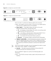
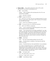
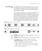
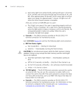
40 CHAPTER 1: INTRODUCTION Figure 12 E1 Digital Line Card (3C10165C) Figure 13 E1 Digital Line Card (3C10165D) Each 3C10165C E1 card has the following lights and connectors: ■ E1 - This RJ-48C connector makes a connection to an ISDN interface channel service unit/data service unit (CSU/DSU). ■ Status Lights - These lights indicate the status of the card's signaling, synchronization, and loop back test. ■ CF - On indicates a Carrier Failure. The card is not receiving carrier signals from the far end of the E1 line. ■ RA - On indicates a Remote Alarm. The far end of the E1 line is not receiving appropriate signaling from the E1 board. ■ LB - On indicates that loop-back testing is going on. ■ Nominal - On indicates ready to send and receive information. ■ 10BASE-T Uplink MDI - This RJ-45 Ethernet connector connects the card to an external LAN hub or switch. If the E1 Digital Line Card is used in a V5000 Gateway Chassis, do not use this connector because the chassis has an Ethernet connector to connect the chassis to the LAN. If you use the Uplink connection, be sure to program the switch or router at the other end for 10BASE-T 10 MB operation. ■ Console - This DB-9 connector provides an RS-232 (DCE) TTY terminal connection for maintenance access. Each 3C10165D E1 Digital Line Card has the following lights and connectors: ■ E1 - This RJ-48C connector makes a patch cord connection to a E1 interface.
-
 1
1 -
2
-
3
-
4
-
5
-
6
-
7
-
8
-
9
-
10
-
11
-
12
-
13
-
14
-
15
-
16
-
17
-
18
-
19
-
20
-
21
-
22
-
23
-
24
-
25
-
26
-
27
-
28
-
29
-
30
-
31
-
32
-
33
-
34
-
 35
35 -
 36
36 -
 37
37 -
 38
38 -
 39
39 -
 40
40 -
 41
41 -
 42
42 -
 43
43 -
 44
44 -
 45
45 -
46
-
47
-
48
-
49
-
50
-
51
-
52
-
53
-
54
-
55
-
56
-
57
-
58
-
59
-
60
-
61
-
62
-
63
-
64
-
65
-
66
-
67
-
68
-
69
-
70
-
71
-
72
-
73
-
74
-
75
-
76
-
77
-
78
-
79
-
80
-
81
-
82
-
83
-
84
-
85
-
86
-
87
-
88
-
89
-
90
-
91
-
92
-
93
-
94
-
95
-
96
-
97
-
98
-
99
-
100
-
101
-
102
-
103
-
104
-
105
-
106
-
107
-
108
-
109
-
110
-
111
-
112
-
113
-
114
-
115
-
116
-
117
-
118
-
119
-
120
-
121
-
122
-
123
-
124
-
125
-
126
-
127
-
128
-
129
-
130
-
131
-
132
-
133
-
134
-
135
-
136
-
137
-
138
-
139
-
140
-
141
-
142
-
143
-
144
-
145
-
146
-
147
-
148
-
149
-
150
-
151
-
152
-
153
-
154
-
155
-
156
-
157
-
158
-
159
-
160
-
161
-
162
-
163
-
164
-
165
-
166
-
167
-
168
-
169
-
170
-
171
-
172
-
173
-
174
-
175
-
176
-
177
-
178
-
179
-
180
-
181
-
182
-
183
-
184
-
185
-
186
-
187
-
188
-
189
-
190
-
191
-
192
-
193
-
194
-
195
-
196
-
197
-
198
-
199
-
200
-
201
-
202
-
203
-
204
-
205
-
206
-
207
-
208
-
209
-
210
-
211
-
212
-
213
-
214
-
215
-
216
-
217
-
218
-
219
-
220
-
221
-
222
-
223
-
224
-
225
-
226
-
227
-
228
-
229
-
230
-
231
-
232
-
233
-
234
-
235
-
236
-
237
-
238
-
239
-
240
-
241
-
242
-
243
-
244
-
245
-
246
-
247
-
248
 |
 |
