3Com 3C10200 NBX Installation Guide - Page 47
Status Lights 1 - 16, Flashing, RJ21x line connector, Handset off-hook for example, a call in progress
 |
View all 3Com 3C10200 manuals
Add to My Manuals
Save this manual to your list of manuals |
Page 47 highlights
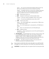
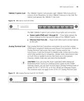
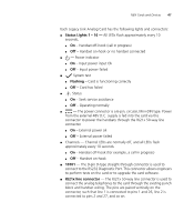
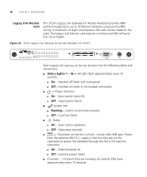
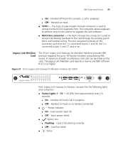
NBX Cards and Devices 47 Each Legacy Link Analog Card has the following lights and connectors: ■ Status Lights 1 - 16 - All LEDs flash approximately every 10 seconds. ■ On - Handset off-hook (call in progress) ■ Off - Handset on-hook or no handset connected ■ - Power indicator ■ On - Input power input Ok ■ Off - Input power failed ■ System test ■ Flashing - Card is functioning correctly ■ Off - Card has failed ■ Status ■ On - Seek service assistance ■ Off - Operating normally ■ - The power connector is a 6-pin, circular, Mini-DIN type. Power from the external 48V D.C. supply is fed into the card via this connector to power the handsets through the RJ21x 50-way line connector. ■ On - External power ok ■ Off - External power failed ■ Channels - Channel LEDs are normally off, and all LEDs flash approximately every 10 seconds ■ On - Handset off-hook (for example, a call in progress) ■ Off - Handset on-hook ■ 10101 - The 9-pin D-type straight-through connector is used to connect to the RS232 Diagnostic Port. This connector allows engineers to perform tests on the card or to upgrade the card software. ■ RJ21x line connector - The RJ21x 50-way line connector is used to connect the analog telephones to the card through the existing punch block and handset wiring. The pins are paired vertically on the connector, such that line 1 is connected to pins 1 and 26, line 2 is connected to pins 2 and 27, and so on.
-
 1
1 -
2
-
3
-
4
-
5
-
6
-
7
-
8
-
9
-
10
-
11
-
12
-
13
-
14
-
15
-
16
-
17
-
18
-
19
-
20
-
21
-
22
-
23
-
24
-
25
-
26
-
27
-
28
-
29
-
30
-
31
-
32
-
33
-
34
-
35
-
36
-
37
-
38
-
39
-
40
-
41
-
 42
42 -
 43
43 -
 44
44 -
 45
45 -
 46
46 -
 47
47 -
 48
48 -
 49
49 -
 50
50 -
 51
51 -
 52
52 -
53
-
54
-
55
-
56
-
57
-
58
-
59
-
60
-
61
-
62
-
63
-
64
-
65
-
66
-
67
-
68
-
69
-
70
-
71
-
72
-
73
-
74
-
75
-
76
-
77
-
78
-
79
-
80
-
81
-
82
-
83
-
84
-
85
-
86
-
87
-
88
-
89
-
90
-
91
-
92
-
93
-
94
-
95
-
96
-
97
-
98
-
99
-
100
-
101
-
102
-
103
-
104
-
105
-
106
-
107
-
108
-
109
-
110
-
111
-
112
-
113
-
114
-
115
-
116
-
117
-
118
-
119
-
120
-
121
-
122
-
123
-
124
-
125
-
126
-
127
-
128
-
129
-
130
-
131
-
132
-
133
-
134
-
135
-
136
-
137
-
138
-
139
-
140
-
141
-
142
-
143
-
144
-
145
-
146
-
147
-
148
-
149
-
150
-
151
-
152
-
153
-
154
-
155
-
156
-
157
-
158
-
159
-
160
-
161
-
162
-
163
-
164
-
165
-
166
-
167
-
168
-
169
-
170
-
171
-
172
-
173
-
174
-
175
-
176
-
177
-
178
-
179
-
180
-
181
-
182
-
183
-
184
-
185
-
186
-
187
-
188
-
189
-
190
-
191
-
192
-
193
-
194
-
195
-
196
-
197
-
198
-
199
-
200
-
201
-
202
-
203
-
204
-
205
-
206
-
207
-
208
-
209
-
210
-
211
-
212
-
213
-
214
-
215
-
216
-
217
-
218
-
219
-
220
-
221
-
222
-
223
-
224
-
225
-
226
-
227
-
228
-
229
-
230
-
231
-
232
-
233
-
234
-
235
-
236
-
237
-
238
-
239
-
240
-
241
-
242
-
243
-
244
-
245
-
246
-
247
-
248
 |
 |
