3Com 3C780 User Guide - Page 34
Site Selection
 |
UPC - 662705029917
View all 3Com 3C780 manuals
Add to My Manuals
Save this manual to your list of manuals |
Page 34 highlights
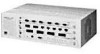
1-8 Overview Figure 1-2 shows the LinkBuilder FDDI hub with the management module and all three types of media modules installed. GRN = SIGNAL DETECT GRN = PORT STATE YEL = LINK ERROR ® PWR UTP PORT MODULE GRN = SIGNAL DETECT GRN = PORT STATE YEL = LINK ERROR ® PWR STP PORT MODULE GRN = SIGNAL DETECT GRN = PORT STATE YEL = LINK ERROR ® PWR FIBER PORT MODULE GRN = SIGNAL DETECT GRN = PORT STATE YEL = LINK ERROR ® OPTICAL BYPASS SERIAL PORT ATTACH MANAGEMENT MODULE B/A FAN HI LOW ® PWR RESET S/M STATUS TOKEN WRAP FAIL TEMP BATT M/M Figure 1-2. The LinkBuilder FDDI Workgroup Hub Site Selection The hub is housed in a 16.8 x 11.6 x 5.2 inch chassis that can be placed on a tabletop or easily mounted in an Electronics Industries Association (EIA) standard 19-inch rack. You can mount more than one hub in a rack depending on your network needs. Included with the chassis are four small rubber pads (to be inserted on the bottom four corners for tabletop placement) and two attachable brackets (to be attached on two sides for rack mounting) for your choice of placement. When selecting a site for the hub, remember that the hub can be connected to an external terminal for initial configuration. In this case you will need room in front of the chassis to place and access the terminal. Instead of attaching a terminal to the hub, you can configure the hub over the network by using the TCP Telnet protocol. You can also access the hub via a modem attached to the serial port.
-
 1
1 -
2
-
3
-
4
-
5
-
6
-
7
-
8
-
9
-
10
-
11
-
12
-
13
-
14
-
15
-
16
-
17
-
18
-
19
-
20
-
21
-
22
-
23
-
24
-
25
-
26
-
27
-
28
-
 29
29 -
 30
30 -
 31
31 -
 32
32 -
 33
33 -
 34
34 -
 35
35 -
 36
36 -
 37
37 -
 38
38 -
 39
39 -
40
-
41
-
42
-
43
-
44
-
45
-
46
-
47
-
48
-
49
-
50
-
51
-
52
-
53
-
54
-
55
-
56
-
57
-
58
-
59
-
60
-
61
-
62
-
63
-
64
-
65
-
66
-
67
-
68
-
69
-
70
-
71
-
72
-
73
-
74
-
75
-
76
-
77
-
78
-
79
-
80
-
81
-
82
-
83
-
84
-
85
-
86
-
87
-
88
-
89
-
90
-
91
-
92
-
93
-
94
-
95
-
96
-
97
-
98
-
99
-
100
-
101
-
102
-
103
-
104
-
105
-
106
-
107
-
108
-
109
-
110
-
111
-
112
-
113
-
114
-
115
-
116
-
117
-
118
-
119
-
120
-
121
-
122
-
123
-
124
-
125
-
126
-
127
-
128
-
129
-
130
-
131
-
132
-
133
-
134
-
135
-
136
-
137
-
138
-
139
-
140
-
141
-
142
-
143
-
144
-
145
-
146
-
147
-
148
-
149
-
150
-
151
-
152
-
153
-
154
-
155
-
156
-
157
-
158
-
159
-
160
-
161
-
162
-
163
-
164
-
165
-
166
-
167
-
168
-
169
-
170
-
171
-
172
-
173
-
174
-
175
-
176
 |
 |
