3Com 3C780 User Guide - Page 37
Management and Media Modules
 |
UPC - 662705029917
View all 3Com 3C780 manuals
Add to My Manuals
Save this manual to your list of manuals |
Page 37 highlights
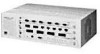
Overview 1-11 Management and Media Modules The hub chassis provides slots for one management module (required) and three media modules, which can be mixed or matched. This section briefly describes each of these modules. (For information about the operation of the management and media modules, see Chapter 5, "Using the Hub.") Management Module The LinkBuilder FDDI Management Module, hereafter called the "management module," must be inserted in slot 0 (the bottom slot) of the hub. Its main purpose is to run the Station Management (SMT) 7.3 software that is required for FDDI operations. The management module provides management and configuration functions through a console interface. Access to this interface is either by a 9-pin RS-232C console serial port for a terminal or modem connection or via a TCP Telnet protocol connection over the network. Figure 1-5 shows the front panel of the management module, which provides a 6-pin mini-DIN receptacle for the connection to an optical bypass switch (OBS). GRN = SIGNAL DETECT GRN = PORT STATE YEL = LINK ERROR ® PWR RESET OPTICAL BYPASS SERIAL PORT ATTACH B/A S/M M/M STATUS TOKEN WRAP MANAGEMENT MODULE FAN HI LOW FAIL TEMP BATT Figure 1-5. Management Module, Front Panel The management module contains a recessed RESET button for reinitializing the hub's software, running the power-on self-tests (POST), and running the flash EPROM. You can also use the RESET button to access the primitive console mode. (Refer to "Accessing Configuration Commands" in Chapter 3 for information on accessing the two console command modes.)
-
 1
1 -
2
-
3
-
4
-
5
-
6
-
7
-
8
-
9
-
10
-
11
-
12
-
13
-
14
-
15
-
16
-
17
-
18
-
19
-
20
-
21
-
22
-
23
-
24
-
25
-
26
-
27
-
28
-
29
-
30
-
31
-
 32
32 -
 33
33 -
 34
34 -
 35
35 -
 36
36 -
 37
37 -
 38
38 -
 39
39 -
 40
40 -
 41
41 -
 42
42 -
43
-
44
-
45
-
46
-
47
-
48
-
49
-
50
-
51
-
52
-
53
-
54
-
55
-
56
-
57
-
58
-
59
-
60
-
61
-
62
-
63
-
64
-
65
-
66
-
67
-
68
-
69
-
70
-
71
-
72
-
73
-
74
-
75
-
76
-
77
-
78
-
79
-
80
-
81
-
82
-
83
-
84
-
85
-
86
-
87
-
88
-
89
-
90
-
91
-
92
-
93
-
94
-
95
-
96
-
97
-
98
-
99
-
100
-
101
-
102
-
103
-
104
-
105
-
106
-
107
-
108
-
109
-
110
-
111
-
112
-
113
-
114
-
115
-
116
-
117
-
118
-
119
-
120
-
121
-
122
-
123
-
124
-
125
-
126
-
127
-
128
-
129
-
130
-
131
-
132
-
133
-
134
-
135
-
136
-
137
-
138
-
139
-
140
-
141
-
142
-
143
-
144
-
145
-
146
-
147
-
148
-
149
-
150
-
151
-
152
-
153
-
154
-
155
-
156
-
157
-
158
-
159
-
160
-
161
-
162
-
163
-
164
-
165
-
166
-
167
-
168
-
169
-
170
-
171
-
172
-
173
-
174
-
175
-
176
 |
 |
