3Com 3C780 User Guide - Page 40
STP Media Port Module, UTP Media Port Module
 |
UPC - 662705029917
View all 3Com 3C780 manuals
Add to My Manuals
Save this manual to your list of manuals |
Page 40 highlights
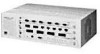
1-14 Overview STP Media Port Module Figure 1-8 shows the front panel of the six-port STP media port module. All of its ports are configured as M ports by default. You can specify any port configuration for the attachment ports, but you must use a special connector called the STP cascade connector to configure the leftmost attachment port as S. To configure the attachment ports as B and A requires two cascade connectors. Refer to Chapter 2 for additional information on the STP cascade connector. GRN = SIGNAL DETECT GRN = PORT STATE YEL = LINK ERROR ® PWR STP PORT MODULE Figure 1-8. STP Media Port Module, Front Panel If you install an STP module in each of the three hub slots, 18 STP ports are available. UTP Media Port Module Figure 1-9 shows the front panel of the UTP media port module, which provides eight ports configured as M ports by default. You can specify any port configuration (B/A, S/M, or M/M) for the attachment ports. No adapter or special connector is needed for the UTP module. If you install three UTP modules in the hub, 24 UTP ports are available. GRN = SIGNAL DETECT GRN = PORT STATE YEL = LINK ERROR ® PWR UTP PORT MODULE Figure 1-9. UTP Media Port Module, Front Panel
-
 1
1 -
2
-
3
-
4
-
5
-
6
-
7
-
8
-
9
-
10
-
11
-
12
-
13
-
14
-
15
-
16
-
17
-
18
-
19
-
20
-
21
-
22
-
23
-
24
-
25
-
26
-
27
-
28
-
29
-
30
-
31
-
32
-
33
-
34
-
 35
35 -
 36
36 -
 37
37 -
 38
38 -
 39
39 -
 40
40 -
 41
41 -
 42
42 -
 43
43 -
 44
44 -
 45
45 -
46
-
47
-
48
-
49
-
50
-
51
-
52
-
53
-
54
-
55
-
56
-
57
-
58
-
59
-
60
-
61
-
62
-
63
-
64
-
65
-
66
-
67
-
68
-
69
-
70
-
71
-
72
-
73
-
74
-
75
-
76
-
77
-
78
-
79
-
80
-
81
-
82
-
83
-
84
-
85
-
86
-
87
-
88
-
89
-
90
-
91
-
92
-
93
-
94
-
95
-
96
-
97
-
98
-
99
-
100
-
101
-
102
-
103
-
104
-
105
-
106
-
107
-
108
-
109
-
110
-
111
-
112
-
113
-
114
-
115
-
116
-
117
-
118
-
119
-
120
-
121
-
122
-
123
-
124
-
125
-
126
-
127
-
128
-
129
-
130
-
131
-
132
-
133
-
134
-
135
-
136
-
137
-
138
-
139
-
140
-
141
-
142
-
143
-
144
-
145
-
146
-
147
-
148
-
149
-
150
-
151
-
152
-
153
-
154
-
155
-
156
-
157
-
158
-
159
-
160
-
161
-
162
-
163
-
164
-
165
-
166
-
167
-
168
-
169
-
170
-
171
-
172
-
173
-
174
-
175
-
176
 |
 |
