3Com 3C780 User Guide - Page 38
Media Modules
 |
UPC - 662705029917
View all 3Com 3C780 manuals
Add to My Manuals
Save this manual to your list of manuals |
Page 38 highlights
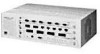
1-12 Overview By interpreting the LEDs on the management module, you can: s Monitor network activity s Determine chassis environmental factors s Discover ring attachment configuration Refer to "Interpreting the LEDs" in Chapter 5 for detailed information about the LEDs on all hub modules. Media Modules Three media modules are currently available. Each module can be placed in any slot, but the modules must be installed from the bottom up, beginning with slot 1. Do not leave empty slots between modules. The two leftmost ports on any module installed in slot 1 are designated as attachment ports. The module in slot 1 is given a default configuration of dual attachment, B/A connection. Only the two leftmost ports of modules installed in slot 1 can be configured. The three modules are: s LinkBuilder FDDI 4-port Optic Module (fiber media port module) s LinkBuilder FDDI 6-port STP Module (STP media port module) s LinkBuilder FDDI 8-port UTP Module (UTP media port module) Fiber Media Port Module The fiber media port module provides four ports, as shown in Figure 1-6. When this module is installed in slot 1, you can configure the attachment ports (the two leftmost ports) as B and A, S and M, or M and M as necessary to support a given attachment. (Refer to Chapter 4 for instructions for configuring the attachment ports.) The remaining two ports are M (master) ports by default.
-
 1
1 -
2
-
3
-
4
-
5
-
6
-
7
-
8
-
9
-
10
-
11
-
12
-
13
-
14
-
15
-
16
-
17
-
18
-
19
-
20
-
21
-
22
-
23
-
24
-
25
-
26
-
27
-
28
-
29
-
30
-
31
-
32
-
 33
33 -
 34
34 -
 35
35 -
 36
36 -
 37
37 -
 38
38 -
 39
39 -
 40
40 -
 41
41 -
 42
42 -
 43
43 -
44
-
45
-
46
-
47
-
48
-
49
-
50
-
51
-
52
-
53
-
54
-
55
-
56
-
57
-
58
-
59
-
60
-
61
-
62
-
63
-
64
-
65
-
66
-
67
-
68
-
69
-
70
-
71
-
72
-
73
-
74
-
75
-
76
-
77
-
78
-
79
-
80
-
81
-
82
-
83
-
84
-
85
-
86
-
87
-
88
-
89
-
90
-
91
-
92
-
93
-
94
-
95
-
96
-
97
-
98
-
99
-
100
-
101
-
102
-
103
-
104
-
105
-
106
-
107
-
108
-
109
-
110
-
111
-
112
-
113
-
114
-
115
-
116
-
117
-
118
-
119
-
120
-
121
-
122
-
123
-
124
-
125
-
126
-
127
-
128
-
129
-
130
-
131
-
132
-
133
-
134
-
135
-
136
-
137
-
138
-
139
-
140
-
141
-
142
-
143
-
144
-
145
-
146
-
147
-
148
-
149
-
150
-
151
-
152
-
153
-
154
-
155
-
156
-
157
-
158
-
159
-
160
-
161
-
162
-
163
-
164
-
165
-
166
-
167
-
168
-
169
-
170
-
171
-
172
-
173
-
174
-
175
-
176
 |
 |
