3Com 3CBLSF50 User Guide - Page 19
Rack-Mounting or Free-Standing, Using the Mounting Kit
 |
UPC - 662705529103
View all 3Com 3CBLSF50 manuals
Add to My Manuals
Save this manual to your list of manuals |
Page 19 highlights
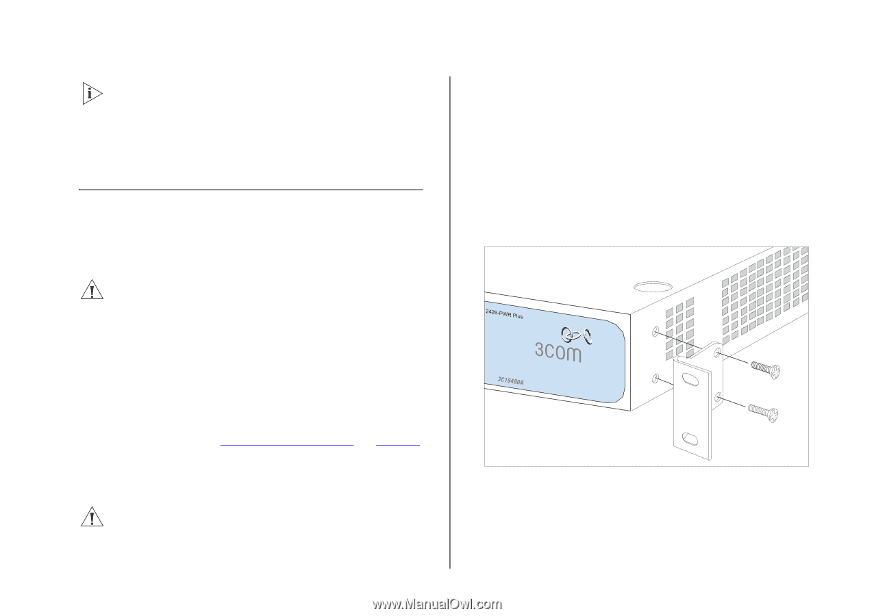
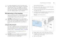
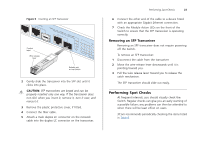
It is always good practice to wear an anti-static wrist strap when installing network equipment, connected to a ground point. If one is not available, try to keep in contact with a grounded rack and avoid touching the unit's ports and connectors, if possible. Static discharge can cause reliability problems in your equipment. Rack-Mounting or Free-Standing The unit can be mounted in a 19-inch equipment rack using the mounting kit, or it can be free standing. Do not place objects on top of the unit or stack. CAUTION: If installing the Switch in a free-standing stack of different size Baseline or Superstack 3 units, the smaller units must be installed above the larger ones. Do not have a free-standing stack of more than six units. Using the Mounting Kit The Switch is supplied with two mounting brackets and four screws. These are used for rack mounting the unit. When mounting the unit, you should take note of the guidelines given in "Positioning the Switch" on page 18. The Switch is 1U (1.7 inches) high and will fit in a standard 19-inch rack. CAUTION: Disconnect all cables from the unit before continuing. Remove the self-adhesive pads from the underside of the unit, if already fitted. Rack-Mounting or Free-Standing 19 To rack-mount the Switch: 1 Place the unit the right way up on a hard, flat surface with the front facing towards you. 2 Locate a mounting bracket over the mounting holes on one side of the unit. 3 Insert the two screws supplied in the mounting kit and fully tighten with a suitable screwdriver. Figure 4 Rack Mounting the Unit 4 Repeat steps 2 and 3 for the other side of the unit. 5 Insert the unit into the 19-inch rack and secure with suitable screws (not provided). 6 Reconnect the cables.
-
 1
1 -
2
-
3
-
4
-
5
-
6
-
7
-
8
-
9
-
10
-
11
-
12
-
13
-
 14
14 -
 15
15 -
 16
16 -
 17
17 -
 18
18 -
 19
19 -
 20
20 -
 21
21 -
 22
22 -
 23
23 -
 24
24 -
25
-
26
-
27
-
28
-
29
-
30
-
31
-
32
-
33
-
34
-
35
-
36
-
37
-
38
-
39
-
40
-
41
-
42
-
43
-
44
-
45
-
46
-
47
-
48
-
49
-
50
-
51
-
52
-
53
-
54
-
55
-
56
-
57
-
58
-
59
-
60
-
61
-
62
-
63
-
64
-
65
-
66
-
67
-
68
-
69
-
70
-
71
-
72
-
73
-
74
-
75
-
76
-
77
-
78
-
79
-
80
-
81
-
82
-
83
-
84
-
85
-
86
-
87
-
88
-
89
-
90
-
91
-
92
-
93
-
94
-
95
-
96
-
97
-
98
-
99
-
100
-
101
-
102
-
103
-
104
-
105
-
106
-
107
-
108
 |
 |