3Com 3CBLSF50 User Guide - Page 20
Montagesatz Anweisungen, Placing Units On Top of Each Other, Supplying Power to the Switch
 |
UPC - 662705529103
View all 3Com 3CBLSF50 manuals
Add to My Manuals
Save this manual to your list of manuals |
Page 20 highlights
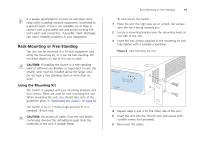
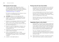
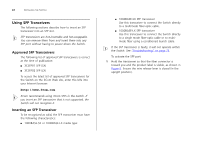
20 INSTALLING THE SWITCH Montagesatz Anweisungen Der Switch wird mit zwei Halterungen und vier Schrauben geliefert. Diese werden für den Einbau in einem Baugruppenträger benutzt. Bei der Montage der Baugruppe beachten Sie die Anweisungen aus "Positioning the Switch" auf page 18. Der Switch ist eine Baueinheit hoch und passt in einen Standard 19'' (Zoll) Baugruppenträger. ACHTUNG: Entfernen Sie alle Kabel, bevor Sie fortsetzen. Entfernen Sie die selbstklebenden Polster (Füße) von der Unterseite der Baugruppe, falls diese bereits angebracht sind. 1 Platzieren Sie die Baugruppe aufrecht auf einer harten, ebenen Fläche mit der Vorderseite Ihnen entgegen. 2 Ordnen Sie eine der Halterungen über den Löchern an der Seite der Baugruppe an. 3 Stecken Sie zwei der mitgelieferten Schrauben in die Löcher und drehen Sie diese mit einem geeigneten Schraubendreher fest. 4 Wiederholen Sie die letzten zwei Schritte auf der anderen Seite der Baugruppe. 5 Führen Sie die Baugruppe in den 19" (Zoll) Baugruppenträger ein und sichern Sie die Baugruppe mit geeigneten Schrauben. (Nicht im Lieferumfang enthalten). 6 Schließen Sie alle Kabel wieder an. Placing Units On Top of Each Other If the Switch units are free-standing, up to six units can be placed one on top of the other. If you are mixing a variety of Baseline and SuperStack units, the smaller units must be positioned at the top. If you are placing Switch units one on top of the other, you must use the self-adhesive rubber pads supplied. Apply the pads to the underside of each Switch, sticking one in the marked area at each corner. Place the Switch units on top of each other, ensuring that the pads of the upper unit line up with the recesses of the lower unit. Supplying Power to the Switch Power problems can be the cause of serious failures and downtime in your network. Ensure that the power input to your system is clean and free from sags and surges to avoid unforeseen network outages. 3Com recommends that you install power conditioning, especially in areas prone to blackout, power dips and electrical storms. The unit is intended to be grounded. Ensure it is connected to earth ground during normal use. Installing proper grounding helps to avoid damage from lightning and power surges. Before powering on the Switch, verify that the network cables and the power cable are securely connected.
-
 1
1 -
2
-
3
-
4
-
5
-
6
-
7
-
8
-
9
-
10
-
11
-
12
-
13
-
14
-
 15
15 -
 16
16 -
 17
17 -
 18
18 -
 19
19 -
 20
20 -
 21
21 -
 22
22 -
 23
23 -
 24
24 -
 25
25 -
26
-
27
-
28
-
29
-
30
-
31
-
32
-
33
-
34
-
35
-
36
-
37
-
38
-
39
-
40
-
41
-
42
-
43
-
44
-
45
-
46
-
47
-
48
-
49
-
50
-
51
-
52
-
53
-
54
-
55
-
56
-
57
-
58
-
59
-
60
-
61
-
62
-
63
-
64
-
65
-
66
-
67
-
68
-
69
-
70
-
71
-
72
-
73
-
74
-
75
-
76
-
77
-
78
-
79
-
80
-
81
-
82
-
83
-
84
-
85
-
86
-
87
-
88
-
89
-
90
-
91
-
92
-
93
-
94
-
95
-
96
-
97
-
98
-
99
-
100
-
101
-
102
-
103
-
104
-
105
-
106
-
107
-
108
 |
 |