3Com 3CBLSF50 User Guide - Page 51
Spanning Tree, Create VLAN2 on both Switch 1 and Switch 2.
 |
UPC - 662705529103
View all 3Com 3CBLSF50 manuals
Add to My Manuals
Save this manual to your list of manuals |
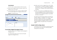
Page 51 highlights
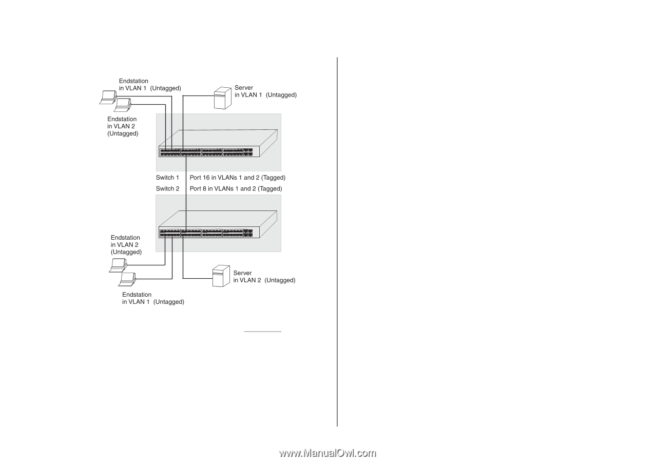
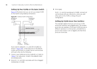
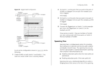
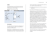
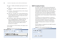
Figure 39 Tagged VLAN Configuration To set up the configuration shown in Figure 39, do the following: 1 Create VLAN2 on both Switch 1 and Switch 2. You need not create VLAN1 since it exists by default. Configuring VLANs 51 2 On Switch 1, set the ports that you want to be part of VLAN2 to Untagged. Set one port (for example, port 16) to Tagged. Click Apply. 3 On Switch 2, set the ports that you want to be part of VLAN2 to Untagged. Set one port (for example, port 8) to Tagged. Click Apply. 4 Connect the Tagged port on Switch 1 (in this example, port 16) to the Tagged port on Switch 2 (in this example, port 8). Those ports on Switch 1 that are members of VLAN2 can now communicate with those ports on Switch 2 that are members of VLAN2. Spanning Tree Spanning tree is a bridge-based system for providing fault tolerance on networks and can be used to detect and disable network loops. The spanning tree ensures that the optimal path is maintained between spanning tree-compliant networked devices by: ■ Disabling redundant paths when the main paths are operational. ■ Enabling redundant paths if the main paths fail. Spanning tree uses a distributed algorithm to select a bridging device that serves as the root of the spanning
-
 1
1 -
2
-
3
-
4
-
5
-
6
-
7
-
8
-
9
-
10
-
11
-
12
-
13
-
14
-
15
-
16
-
17
-
18
-
19
-
20
-
21
-
22
-
23
-
24
-
25
-
26
-
27
-
28
-
29
-
30
-
31
-
32
-
33
-
34
-
35
-
36
-
37
-
38
-
39
-
40
-
41
-
42
-
43
-
44
-
45
-
 46
46 -
 47
47 -
 48
48 -
 49
49 -
 50
50 -
 51
51 -
 52
52 -
 53
53 -
 54
54 -
 55
55 -
 56
56 -
57
-
58
-
59
-
60
-
61
-
62
-
63
-
64
-
65
-
66
-
67
-
68
-
69
-
70
-
71
-
72
-
73
-
74
-
75
-
76
-
77
-
78
-
79
-
80
-
81
-
82
-
83
-
84
-
85
-
86
-
87
-
88
-
89
-
90
-
91
-
92
-
93
-
94
-
95
-
96
-
97
-
98
-
99
-
100
-
101
-
102
-
103
-
104
-
105
-
106
-
107
-
108
 |
 |