3Com 3CBLSF50 User Guide - Page 46
Setup, Modify VLAN, CAUTION
 |
UPC - 662705529103
View all 3Com 3CBLSF50 manuals
Add to My Manuals
Save this manual to your list of manuals |
Page 46 highlights
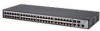
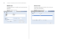
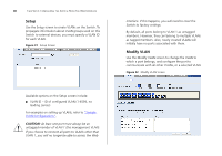
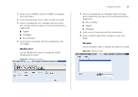
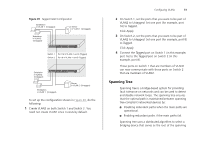
46 CHAPTER 4: CONFIGURING THE SWITCH FROM THE WEB INTERFACE Setup Use the Setup screen to create VLANs on the Switch. To propagate information about VLAN groups used on this Switch to external devices, you must specify a VLAN ID for each VLAN. Figure 31 Setup Screen Available options on the Setup screen include: ■ VLAN ID - ID of configured VLAN (1-4094, no leading zeroes) For examples on setting up VLANs, refer to "Sample VLAN Configurations". CAUTION: At least one port must always be an untagged member of VLAN 1 (the management VLAN). If you choose to connect all ports to VLANs other than VLAN 1, you will no longer be able to access the Web interface. If this happens, you will need to reset the Switch to factory settings. By default, all ports belong to VLAN 1 as untagged members. However, they can belong to multiple VLANs as tagged members. Also, newly created VLANs will initially have no ports associated with them. Modify VLAN Use the Modify VLAN screen to change the VLAN to which a port belongs, and configure the port to communicate with all other VLANs, or a selected VLAN. Figure 32 Modify VLAN Screen
-
 1
1 -
2
-
3
-
4
-
5
-
6
-
7
-
8
-
9
-
10
-
11
-
12
-
13
-
14
-
15
-
16
-
17
-
18
-
19
-
20
-
21
-
22
-
23
-
24
-
25
-
26
-
27
-
28
-
29
-
30
-
31
-
32
-
33
-
34
-
35
-
36
-
37
-
38
-
39
-
40
-
 41
41 -
 42
42 -
 43
43 -
 44
44 -
 45
45 -
 46
46 -
 47
47 -
 48
48 -
 49
49 -
 50
50 -
 51
51 -
52
-
53
-
54
-
55
-
56
-
57
-
58
-
59
-
60
-
61
-
62
-
63
-
64
-
65
-
66
-
67
-
68
-
69
-
70
-
71
-
72
-
73
-
74
-
75
-
76
-
77
-
78
-
79
-
80
-
81
-
82
-
83
-
84
-
85
-
86
-
87
-
88
-
89
-
90
-
91
-
92
-
93
-
94
-
95
-
96
-
97
-
98
-
99
-
100
-
101
-
102
-
103
-
104
-
105
-
106
-
107
-
108
 |
 |