Asus RAMPAGE V EXTREME User Guide - Page 55
Ig Ig
 |
View all Asus RAMPAGE V EXTREME manuals
Add to My Manuals
Save this manual to your list of manuals |
Page 55 highlights
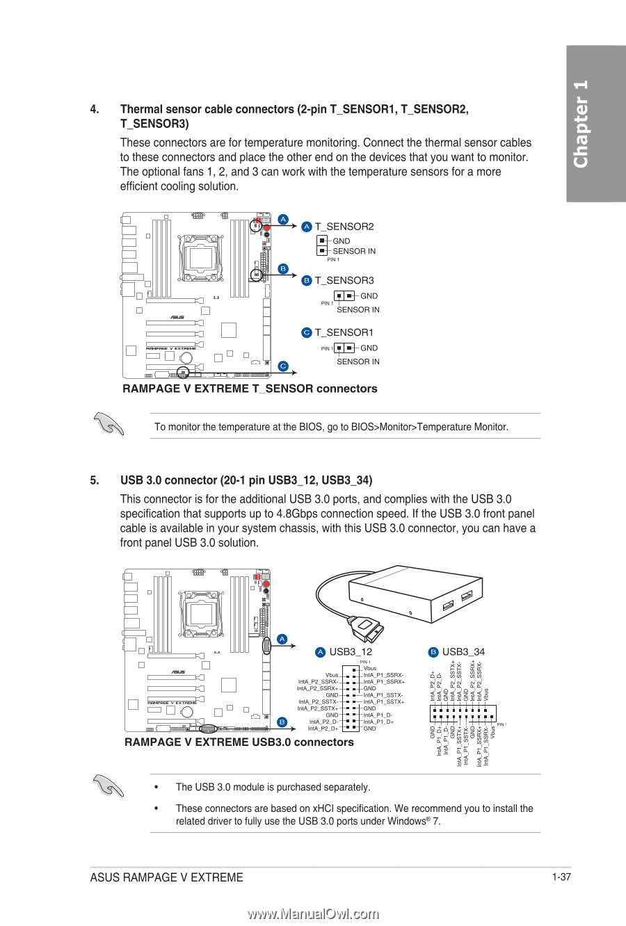
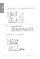
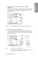
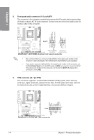
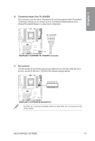
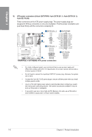
4. Thermal sensor cable connectors (2-pin T_SENSOR1, T_SENSOR2, cu T_SENSOR3) These connectors are for temperature monitoring. Connect the thermal sensor cables to to these connectors and place the other end on the devices that you want to monitor. The optional fans 1, 2, and 3 can work with the temperature sensors for a more U efficient cooling solution. C)T_SENSOR2 GND if SENSOR IN PIN 1 T_SENSOR3 GND PIN 1 SENSOR IN eT_SENSOR1 PIN 1 - GND SENSOR IN MEW RAMPAGE V EXTREME T_SENSOR connectors To monitor the temperature at the BIOS, go to BIOS>Monitor>Temperature Monitor. 5. USB 3.0 connector (20-1 pin USB3_12, USB3_34) This connector is for the additional USB 3.0 ports, and complies with the USB 3.0 specification that supports up to 4.8Gbps connection speed. If the USB 3.0 front panel cable is available in your system chassis, with this USB 3.0 connector, you can have a front panel USB 3.0 solution. I I ci USB3_12 PIX 1 ._ Vbus_. ._IntVobkuis.1_SSRX- 'MA P2_SSFIX--. .- INA P1_SSRX., IntA_P2_SSR)(+-. .-GNI) GND-. .- InULPI_SSTX- IntA_P2_8STX--• .- IntA_Pl_SSTX+ IntA_P2_SSTX+-• . - GNI) O CND-. .- Ira, P1 D. IntAJ2_D--. IntA_P2_0+ -• . - "A- Pi.- GNI) D+ RAMPAGE V EXTREME USB3.0 connectors 0 USB3_34 g g ..... 2 55 c.) 4 44 4,4 2 II; 4 ' illiiiiii i i i i i i i i i i .., g51dini • The USB 3.0 module is purchased separately. • These connectors are based on xHCI specification. We recommend you to install the related driver to fully use the USB 3.0 ports under Windows ® 7. ASUS RAMPAGE V EXTREME 1-37
-
 1
1 -
2
-
3
-
4
-
5
-
6
-
7
-
8
-
9
-
10
-
11
-
12
-
13
-
14
-
15
-
16
-
17
-
18
-
19
-
20
-
21
-
22
-
23
-
24
-
25
-
26
-
27
-
28
-
29
-
30
-
31
-
32
-
33
-
34
-
35
-
36
-
37
-
38
-
39
-
40
-
41
-
42
-
43
-
44
-
45
-
46
-
47
-
48
-
49
-
 50
50 -
 51
51 -
 52
52 -
 53
53 -
 54
54 -
 55
55 -
 56
56 -
 57
57 -
 58
58 -
 59
59 -
 60
60 -
61
-
62
-
63
-
64
-
65
-
66
-
67
-
68
-
69
-
70
-
71
-
72
-
73
-
74
-
75
-
76
-
77
-
78
-
79
-
80
-
81
-
82
-
83
-
84
-
85
-
86
-
87
-
88
-
89
-
90
-
91
-
92
-
93
-
94
-
95
-
96
-
97
-
98
-
99
-
100
-
101
-
102
-
103
-
104
-
105
-
106
-
107
-
108
-
109
-
110
-
111
-
112
-
113
-
114
-
115
-
116
-
117
-
118
-
119
-
120
-
121
-
122
-
123
-
124
-
125
-
126
-
127
-
128
-
129
-
130
-
131
-
132
-
133
-
134
-
135
-
136
-
137
-
138
-
139
-
140
-
141
-
142
-
143
-
144
-
145
-
146
-
147
-
148
-
149
-
150
-
151
-
152
-
153
-
154
-
155
-
156
-
157
-
158
-
159
-
160
-
161
-
162
-
163
-
164
-
165
-
166
-
167
-
168
-
169
-
170
-
171
-
172
-
173
-
174
-
175
-
176
-
177
-
178
-
179
-
180
-
181
-
182
-
183
-
184
-
185
-
186
-
187
-
188
-
189
-
190
-
191
-
192
-
193
-
194
-
195
-
196
-
197
-
198
-
199
-
200
-
201
-
202
-
203
-
204
-
205
-
206
-
207
-
208
-
209
-
210
-
211
-
212
-
213
-
214
-
215
-
216
-
217
-
218
-
219
-
220
-
221
-
222
-
223
-
224
-
225
-
226
-
227
-
228
-
229
-
230
 |
 |