Asus RAMPAGE V EXTREME User Guide - Page 65
Basic, installation
 |
View all Asus RAMPAGE V EXTREME manuals
Add to My Manuals
Save this manual to your list of manuals |
Page 65 highlights
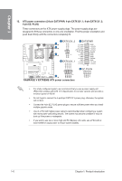
Basic installation 2.1 2.1.1 Building your PC system Motherboard installation The diagrams in this section are for reference only. The motherboard layout may vary with N models, but the installation steps are the same for all models. +CaT, 1. Install the ASUS Q-Shield to the chassis rear I/O panel. a 10 U o k7a0o0g700,o0,og,,00,00g40no0olLi60oOo000i0. tosogsosoossso9, c oo 8 a CD 2. Place the motherboard into the chassis ensuring that its rear I/O ports are aligned to the chassis' rear I/O panel. ASUS RAMPAGE V EXTREME 2-1
-
 1
1 -
2
-
3
-
4
-
5
-
6
-
7
-
8
-
9
-
10
-
11
-
12
-
13
-
14
-
15
-
16
-
17
-
18
-
19
-
20
-
21
-
22
-
23
-
24
-
25
-
26
-
27
-
28
-
29
-
30
-
31
-
32
-
33
-
34
-
35
-
36
-
37
-
38
-
39
-
40
-
41
-
42
-
43
-
44
-
45
-
46
-
47
-
48
-
49
-
50
-
51
-
52
-
53
-
54
-
55
-
56
-
57
-
58
-
59
-
 60
60 -
 61
61 -
 62
62 -
 63
63 -
 64
64 -
 65
65 -
 66
66 -
 67
67 -
 68
68 -
 69
69 -
 70
70 -
71
-
72
-
73
-
74
-
75
-
76
-
77
-
78
-
79
-
80
-
81
-
82
-
83
-
84
-
85
-
86
-
87
-
88
-
89
-
90
-
91
-
92
-
93
-
94
-
95
-
96
-
97
-
98
-
99
-
100
-
101
-
102
-
103
-
104
-
105
-
106
-
107
-
108
-
109
-
110
-
111
-
112
-
113
-
114
-
115
-
116
-
117
-
118
-
119
-
120
-
121
-
122
-
123
-
124
-
125
-
126
-
127
-
128
-
129
-
130
-
131
-
132
-
133
-
134
-
135
-
136
-
137
-
138
-
139
-
140
-
141
-
142
-
143
-
144
-
145
-
146
-
147
-
148
-
149
-
150
-
151
-
152
-
153
-
154
-
155
-
156
-
157
-
158
-
159
-
160
-
161
-
162
-
163
-
164
-
165
-
166
-
167
-
168
-
169
-
170
-
171
-
172
-
173
-
174
-
175
-
176
-
177
-
178
-
179
-
180
-
181
-
182
-
183
-
184
-
185
-
186
-
187
-
188
-
189
-
190
-
191
-
192
-
193
-
194
-
195
-
196
-
197
-
198
-
199
-
200
-
201
-
202
-
203
-
204
-
205
-
206
-
207
-
208
-
209
-
210
-
211
-
212
-
213
-
214
-
215
-
216
-
217
-
218
-
219
-
220
-
221
-
222
-
223
-
224
-
225
-
226
-
227
-
228
-
229
-
230
 |
 |

Basic
installation
2.1
Building
your
PC
system
2.1.1
Motherboard
installation
The
diagrams
in
this
section
are
for
reference
only.
The
motherboard
layout
may
vary
with
models,
but
the
installation
steps
are
the
same
for
all
models.
1.
Install
the
ASUS
Q
-Shield
to
the
chassis
rear
I/O
panel.
kgggliOi.
o
7
07
,
0
o
,o
,
00
,40
60
0
000
0
c
8
ao
00
0,0
00
n
oo
Lo
o
o
o
to
so
go
s
s
os
o
ss
o9,
a
CD
2.
Place
the
motherboard
into
the
chassis
ensuring
that
its
rear
I/O
ports
are
aligned
to
the
chassis'
rear
I/O
panel.
ASUS
RAMPAGE
V
EXTREME
2-1