Beretta Sako 85 Finnlight ST Sako 85 User Manual - Page 19
Single-set Trigger Mechanism, Bolt Disassembly And Reassembly, Cleaning After Use, Cleaning
 |
View all Beretta Sako 85 Finnlight ST manuals
Add to My Manuals
Save this manual to your list of manuals |
Page 19 highlights
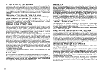
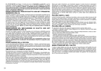
TRIGGER ADJUSTMENT (Fig. 8) - The trigger pull can be adjusted with an 2.5 mm Allen key from 10 to 20 Newtons (2 to 4 lbs) with the screw 1. - Turning the screw clockwise will increase the pressure. Turning the screw counterclockwise will reduce the pressure. WARNING! FOR SAFETY REASONS DO NOT ATTEMPT TO REDUCE TRIGGER PRESSURE BELOW 10 NEWTONS (2 LBS). SINGLE-SET TRIGGER MECHANISM For use as a normal single-stage trigger, squeeze rearwards in the normal fashion. The trigger mechanism can also be "SET" by pushing the trigger forward until it stops. The rifle can now be fired with a very light pressure on the trigger. WARNING! WHEN THE TRIGGER IS IN THE "SET" POSITION, THE RIFLE MUST BE HANDLED WITH EXTREME CARE, AS ANY SHOCK OR VIBRATION CAN DISCHARGE THE RIFLE. To return trigger to the "UNSET" position, the safest method is to engage the safety catch or open the bolt. If the rifle is cocked, with the safety catch on, the trigger CANNOT be put into the "SET" position. NOTE! When the safety catch is in the "ON" position, it locks the trigger mechanism and the bolt. The rifle can be cocked only by pressing the bolt handle release button, located in front of the safety catch, and by opening the bolt to cock the mechanism. TRIGGER ADJUSTMENT (Fig. 9) Should you wish to alter the trigger pressure, the safest way is to detach the stock first. To do this, remove the trigger guard fastening screws. Trigger pressure can also be adjusted, with a proper tool, through the magazine opening, as shown in Fig. 8. The trigger mechanism is constructed for 10 - 20 Newtons (2 - 4 lbs) trigger weight in the single-stage position. The trigger weight is adjusted to 13 - 15 Newtons (3 lbs) at the factory. To be sure that the single-set trigger operates correctly in all circumstances, the trigger weight should not be increased. The trigger weight can be adjusted by the means of screw (1) with an 2.5 mm Allen key. Turning the screw clockwise will increase the trigger weight. NOTE! Screw (1) is self-locking and requires a proper tool. SET-TRIGGER ADJUSTMENT (Fig. 9) When the trigger is in the "SET" position, the trigger weight is 2 - 2.5 Newtons (7 - 9 oz.) and cannot be adjusted. The screw (2) adjusts the gap between the trigger and the plunger of the trigger weight spring. This gap feels as creep in the unset stage and should be as small as possible. Preferably the screw should lightly touch the plunger. On the other hand, if the pressure between the screw (2) and the plunger is too heavy, it may prevent the set-trigger from working. NOTE! Screw (2) is self-locking and unnecessary adjustments should be avoided to keep the self-locking device in good condition. SAFETY ADJUSTMENT The safety is permanently adjusted at the factory. However, if the trigger, trigger sear or safety lever has to be changed, the safety must be re-adjusted. For this operation the trigger mechanism must be returned to the factory in Finland. BOLT DISASSEMBLY AND REASSEMBLY It is not generally necessary to disassemble the bolt. But, in case too much oil has accumulated inside the bolt, which can cause stiffness or misfires, it should be cleaned. If you intend to use the firearm in cold weather, removal of excess oil in the bolt is particularly important. Having removed the bolt from the firearm, the firing pin assembly is removed by turning the bolt shroud clockwise until its locking notches are disengaged from the bolt body and the bolt shroud springs backwards. Having done this, the bolt shroud and firing pin assembly, with the spring and spring guide, can be removed from the bolt. Normally it is not necessary to disassemble the bolt any further for cleaning purposes. Having cleaned the bolt, reverse the order to reassemble. First insert the firing pin assembly, with the spring and spring guide, into place with the bolt shroud so, that cocking piece is on the opposite side of the bolt handle and the locking notches of the bolt shroud are fitted into position at the rear end of the bolt body (Fig. 10). The bolt shroud is then pushed against the bolt, and simultaneously turned counter-clockwise, until the cocking piece cam stops in the notch (C in Fig. 11) before the cocking slope. CLEANING AFTER USE Before commencing cleaning, check that all cartridges have been removed both from the magazine and the chamber. Remove the bolt and push an oily cleaning cloth through the bore. After this the rifle can be stored in this condition for some time. Clean the bolt, as well as the other external metal parts lightly with an oily cloth. Maintenance should not be neglected even in case of the "All-weather" or "Stainless" models, as the steel may still corrode. CLEANING THE BARREL The following procedure should be used when cleaning the barrel: - Always push the cleaning/oiling patch from the breech end. - Do not scrub the barrel, simply push the patch through the barrel and out through the muzzle. Repeat as necessary. - Use only absolutely straight, sturdy and smooth cleaning rods. - It is also advisable to occasionally remove copper fouling from the barrel. This looks like copper from bullet jacket when the front part of the bore is examined. There are various solvents and mechanical cleaners for this purpose, and we recommend that the instructions given by their manufacturers, are followed. Badly fouled barrels can shoot inaccurately and will corrode much easier than carefully cleaned ones. - After thorough cleaning, the barrel should be lightly oiled. MAINTENANCE OF THE STOCK The stock has been treated with oil, which stops moisture from being absorbed and prevents warping. Normally it is necessary to just dry the stock after use and keep the inside of the stock oiled. To keep the oil-finish in good condition, it should be wiped over occasionally with original SAKO stock oil. The synthetic stock of the "All-weather" models do not need any special maintenance. 19
-
 1
1 -
2
-
3
-
4
-
5
-
6
-
7
-
8
-
9
-
10
-
11
-
12
-
13
-
 14
14 -
 15
15 -
 16
16 -
 17
17 -
 18
18 -
 19
19 -
 20
20 -
 21
21 -
 22
22 -
 23
23 -
 24
24 -
25
-
26
-
27
-
28
-
29
-
30
-
31
-
32
-
33
-
34
-
35
-
36
-
37
-
38
-
39
-
40
-
41
-
42
-
43
-
44
-
45
-
46
-
47
-
48
-
49
-
50
-
51
-
52
-
53
-
54
-
55
-
56
-
57
-
58
-
59
-
60
 |
 |