Bosch WTVC5530UC User Guide - Page 11
Installation, Types
 |
View all Bosch WTVC5530UC manuals
Add to My Manuals
Save this manual to your list of manuals |
Page 11 highlights
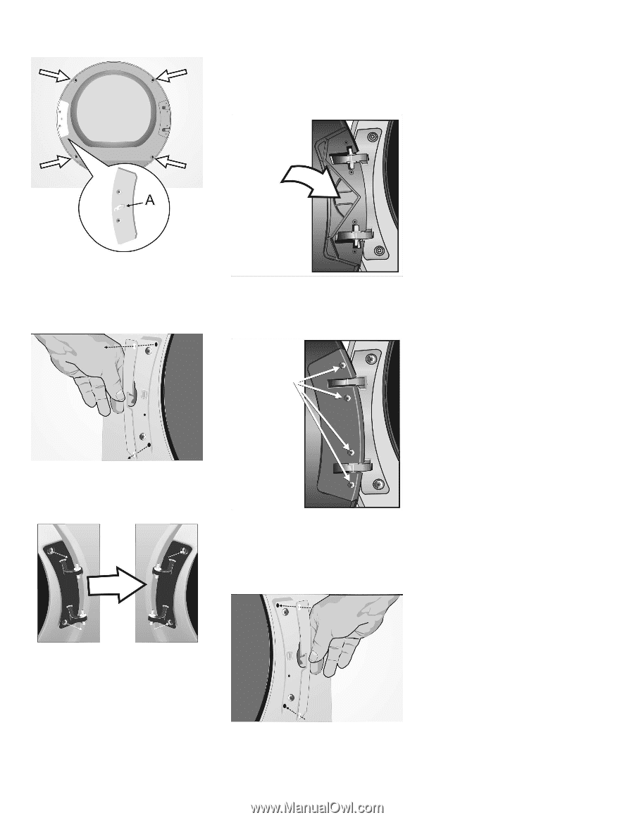
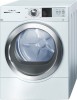
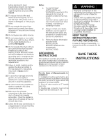
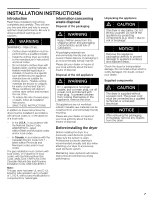
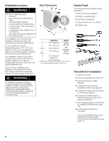
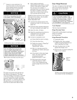
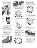
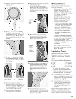
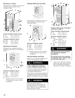
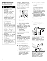
19. Reinsert and tighten the four front ring screws. 20. Remove the two screws holding the plastic cover plate over the left hand hinge mounting position on the dryer housing. Remove the plate and set it aside with the two screws. 21. Remove the two screws holding the metal door hinge to the dryer housing. Remove the hinge from the housing. Right Hand to Left Hand 22. Reattach the door hinge to the dryer housing at the left side of the dryer door opening. Tighten both screws completely, making sure they hold the hinge securely. 23. The door is now ready to be mounted back on the dryer. 24. Reinstall the dryer door by sliding it onto the hinge pins. Avoid allowing the four plastic bushings to fall off the hinge pins. If any fall off, reinstall them on the hinge pins prior to reinstalling the dryer door. reinstall the dryer door 25. Reinstall the hinge cover plate removed in step 4. Insert and tighten the 4 screws holding the hinge cover plate in place. reinstall four screws and tighten securely 26. Install the plastic cover plate over the original hinge position at the right hand side of the dryer door opening. Insert and tighten the two screws holding the plate in place. 27. Test that the door opens and closes properly. The door should latch securely. The hinge reversal process is complete. Minimum Distances Important information concerning minimum distances: - Depending on the location of the exhaust air connection, an additional minimum distance of 5½ inch (14 cm) must be provided on this side, the side the connection is on, for ducts/brackets (see page 18). - Benefits of maintaining greater distance (clearances) than the minimum shown include: S more air cools the dryer, keeps the dryer from overheating, and improves drying performance. S reduction of the risk of mold formation behind the appliance. S reduced noise transmission S facilitation of installation and service. - If the dryer is installed in a small room, the doors of the room must be fitted with vents of the specified minimum size. Refer to the following illustrations of enclosed installations for additional information. - Allow additional clearance for door, wall and window molding where necessary. Installation Types Observe the following minimum clearances between the dryer and adjacent surfaces for all installation types. Minimum Installation Clearances A Sides B Top C Rear* D Front 0.25 in. (6.4 mm) 0.25 in. (6.4 mm) 5.25 in. (13.4 cm) 0.50 in. (12.8 mm) * as close to wall as venting or water connection will allow. If installed with a washer, the larger rear clearance for dryer venting is required for the laundry pair. q Units are designed so that the dryer can be stacked on top of the washer using one of the stacking kits shown on page 19. q Units are designed to allow for under-counter installation See required dimensions in undercounter installation section on page 13. Height measurements shown in this section are with the dryer feet at minimum extension (turned in all the way up against the base of the dryer). 11
-
 1
1 -
2
-
3
-
4
-
5
-
 6
6 -
 7
7 -
 8
8 -
 9
9 -
 10
10 -
 11
11 -
 12
12 -
 13
13 -
 14
14 -
 15
15 -
 16
16 -
17
-
18
-
19
-
20
-
21
-
22
-
23
-
24
-
25
-
26
-
27
-
28
-
29
-
30
-
31
-
32
-
33
-
34
-
35
-
36
-
37
-
38
-
39
-
40
-
41
-
42
-
43
-
44
-
45
-
46
-
47
-
48
-
49
-
50
-
51
-
52
-
53
-
54
-
55
-
56
-
57
-
58
-
59
-
60
-
61
-
62
-
63
-
64
-
65
-
66
-
67
-
68
-
69
-
70
-
71
-
72
-
73
-
74
-
75
-
76
-
77
-
78
-
79
-
80
-
81
-
82
-
83
-
84
-
85
-
86
-
87
-
88
-
89
-
90
-
91
-
92
-
93
-
94
-
95
-
96
-
97
-
98
-
99
-
100
-
101
-
102
-
103
-
104
 |
 |