Bosch WTVC5530UC User Guide - Page 15
Warning, Caution
 |
View all Bosch WTVC5530UC manuals
Add to My Manuals
Save this manual to your list of manuals |
Page 15 highlights
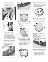
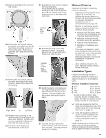
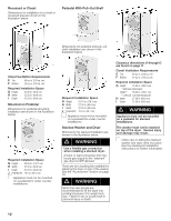
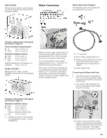
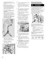
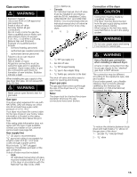
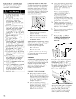
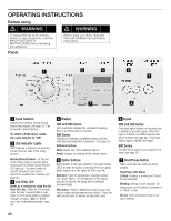
Gas connection d WARNING Explosion hazard! Use a new AGA or CSA approved gas supply line. Install a shutĆoff valve. Securely tighten all gas connections. Do not crush or kink the gas line. Have a qualified person make sure gas pressure does not exceed 14 in. W.C./ 3.49 kPa/ 0.506 psig. (Natural Gas and Propane). Example of a qualified person include: - licensed heating personnel, - authorized gas supplier personnel, - authorized service personnel. Failure to do so can result in explosion or fire. Risk of death or injury! All gas line connections must be tested for leaks prior to appliance operation. Apply soapy water to gas line connections and check for formation of new bubbles. Bubbles indicate a leak! When installing the gas supply to the gas dryer inlet pipe, do not exceed 26 ft-lb (35 Nm). d WARNING Never use an open flame to test for gas leaks. Gas type This dryer when equipped for use with NATURAL GAS will employ an orifice size 46 and will have a gas outlet pressure of 3.5 in. W.C. Your dryer must have the correct valve for the type of gas in your home. Valve information is located on the rating plate behind the door below the port hole. If the ratingĆplate information does not agree with the type of gas available, contact your dealer or our customer service team (see page 32). Gas supply line 1/2" I.D. pipe is recommended. 3le/n8"gtahpspuronvdeedr tubing is 20 ft (6.1 acceptable m) if local for codes and gas supplier permit. Mtapusptiningc, liumdme e1d/8ia" tNelPyTuppslutgregaemd of the gas connection. A shut off valve must be included: - USA: An individual manual shutĆoff valve must be installed within 6 ft (1.8 m) of the dryer in accordance with the National Fuel Gas Code, ANSI Z223.1/NFPA 54. - Canada: An individual manual shutĆoff valve must be installed in accordance with the B149, Installation Codes, CAN/CSA B149.1 and CAN/CSA B149.2. It is recommended that an individual manual shutĆoff valve be installed within 6 ft (1.8 m) of the dryer. 5 43 2 1 1 1 ć 1/2" NPT gas supply line 2 ć Gas shutĆoff valve 3 ć 1/8" NPT plugged tapping 4 ć 3/8" pipe to flare adapter fitting 5 ć 3/8" flexible gas connector (to the dryer) The shutĆoff valve should be easy to reach for opening and closing. Dryer gas pipe The gas pipe that comes out through the rear of the pipe thread. dryer has a 3/8" male Note: The dryer must be checked for proper operation whenever the gas connections have been broken. Connection of the dryer d CAUTION Connection must be made by a qualified technician. The dryer must be disconnected from the gas supply piping system during pressure testing. When using for the first time make sure that there is no air in the piping system. d WARNING Do not use copper pipes and tubing if connected to natural gas. d WARNING Use a flexible gas connection when installing a stacked dryer. A hard, or rigid connection from the house gas supply to the stacked" gas dryer is NOT allowed. The connection may be different, according to the supply line type, size and location. If local codes permit, use a flexible stainless steel connector (Design certified by the America Gas Association or CSA International) to connect the dryer. 1 2 To reduce the distance between body sheet and wall the gas pipe of itnhsetadllraye3r/.8" elbow on 1 ć gas pipe (3/8" male pipe thread) 2 ć 3/8" elbow 15
-
 1
1 -
2
-
3
-
4
-
5
-
6
-
7
-
8
-
9
-
 10
10 -
 11
11 -
 12
12 -
 13
13 -
 14
14 -
 15
15 -
 16
16 -
 17
17 -
 18
18 -
 19
19 -
 20
20 -
21
-
22
-
23
-
24
-
25
-
26
-
27
-
28
-
29
-
30
-
31
-
32
-
33
-
34
-
35
-
36
-
37
-
38
-
39
-
40
-
41
-
42
-
43
-
44
-
45
-
46
-
47
-
48
-
49
-
50
-
51
-
52
-
53
-
54
-
55
-
56
-
57
-
58
-
59
-
60
-
61
-
62
-
63
-
64
-
65
-
66
-
67
-
68
-
69
-
70
-
71
-
72
-
73
-
74
-
75
-
76
-
77
-
78
-
79
-
80
-
81
-
82
-
83
-
84
-
85
-
86
-
87
-
88
-
89
-
90
-
91
-
92
-
93
-
94
-
95
-
96
-
97
-
98
-
99
-
100
-
101
-
102
-
103
-
104
 |
 |