Brother International RH-9820 Instruction Manual - English - Page 27
Connecting the cords, 3-14-1. Connecting the connectors inside the control box
 |
View all Brother International RH-9820 manuals
Add to My Manuals
Save this manual to your list of manuals |
Page 27 highlights
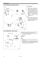
3-14. Connecting the cords 3. INSTALLATION 3-14-1. Connecting the connectors inside the control box 0365B 1. Remove the eight screws (1), and then remove the control box cover (2). 2. Gently tilt back the machine head. 3. Pass the cord bundle through the table hole, and then pass it into the control box through the hole in the rear of the control box. 4. Pass the hammer valve harness (3) into the control box through the hole in the rear of the control box. (4) Hammer valve 5. Insert each of the connectors as shown in the illustration and table on pages 19 and 20. NOTE: • Check that the connectors are facing the correct way, and then insert them firmly until they lock into place. • Secure the cables with fastening bands and cord clamps, while being careful not to pull on the connectors. 0524B (Continued on next page) RH-9820 18
-
 1
1 -
2
-
3
-
4
-
5
-
6
-
7
-
8
-
9
-
10
-
11
-
12
-
13
-
14
-
15
-
16
-
17
-
18
-
19
-
20
-
21
-
 22
22 -
 23
23 -
 24
24 -
 25
25 -
 26
26 -
 27
27 -
 28
28 -
 29
29 -
 30
30 -
 31
31 -
 32
32 -
33
-
34
-
35
-
36
-
37
-
38
-
39
-
40
-
41
-
42
-
43
-
44
-
45
-
46
-
47
-
48
-
49
-
50
-
51
-
52
-
53
-
54
-
55
-
56
-
57
-
58
-
59
-
60
-
61
-
62
-
63
-
64
-
65
-
66
-
67
-
68
-
69
-
70
-
71
-
72
-
73
-
74
-
75
-
76
-
77
-
78
-
79
-
80
-
81
-
82
-
83
-
84
-
85
-
86
-
87
-
88
-
89
-
90
-
91
-
92
-
93
-
94
-
95
-
96
-
97
-
98
-
99
-
100
-
101
-
102
-
103
-
104
-
105
-
106
-
107
-
108
-
109
-
110
-
111
-
112
-
113
-
114
-
115
-
116
-
117
-
118
-
119
-
120
-
121
-
122
-
123
-
124
-
125
 |
 |
