Cisco 7600 SIP 200 Hardware Installation Guide - Page 101
-Port Gigabit Ethernet SPA LEDs, 2-Port Gigabit Ethernet SPA Cables and Connectors
 |
UPC - 746320961286
View all Cisco 7600 SIP 200 manuals
Add to My Manuals
Save this manual to your list of manuals |
Page 101 highlights
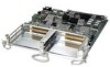
Chapter 3 Overview: Cisco 7600 Series Router Shared Port Adapters 2-Port Gigabit Ethernet SPA Overview 2-Port Gigabit Ethernet SPA LEDs The 2-Port Gigabit Ethernet SPA has two types of LEDs. There is an A/L LED for each port and one STATUS LED as shown in Figure 3-47. Figure 3-47 2-Port Gigabit Ethernet SPA Faceplate 1 0 1 0 1 277959 A/L A/L A/L A/L STATUS SPA-2X1GE--V2 2 1 A/L LED (for each interface) 2 STATUS LED (for entire SPA) The 2-Port Gigabit Ethernet SPA LEDs are described in Table 3-29. Table 3-29 2-Port Gigabit Ethernet SPA LEDs LED Label A/L STATUS Color Off Green Amber Off Green Amber State Off On On Off On On Meaning Port is not enabled. The port is enabled and the link is up. The port is enabled and the link is down. SPA power is off. SPA is ready and operational. SPA power is on and good, and SPA is being configured. 2-Port Gigabit Ethernet SPA Cables and Connectors The interface connectors on the 2-Port Gigabit Ethernet SPA are two individual fiber optic receivers that support SFP modules. Each port can send and receive traffic using the optical fiber connections. SFP Module Connections The small form-factor pluggable (SFP) module is an input/output (I/O) device that plugs into the Gigabit Ethernet optical slots on the 2-Port Gigabit Ethernet SPA, linking the port with a 1000BASE-X fiber-optic network. Note The 2-Port Gigabit Ethernet SPA will only accept the SFP modules listed as supported in this document. An SFP check is run every time an SFP module is inserted into the 2-Port Gigabit Ethernet SPA and only SFP modules that pass this check will be usable by the 2-Port Gigabit Ethernet SPA. OL-5052-14 Cisco 7600 Series Router SIP, SSC, and SPA Hardware Installation Guide 3-55
-
 1
1 -
2
-
3
-
4
-
5
-
6
-
7
-
8
-
9
-
10
-
11
-
12
-
13
-
14
-
15
-
16
-
17
-
18
-
19
-
20
-
21
-
22
-
23
-
24
-
25
-
26
-
27
-
28
-
29
-
30
-
31
-
32
-
33
-
34
-
35
-
36
-
37
-
38
-
39
-
40
-
41
-
42
-
43
-
44
-
45
-
46
-
47
-
48
-
49
-
50
-
51
-
52
-
53
-
54
-
55
-
56
-
57
-
58
-
59
-
60
-
61
-
62
-
63
-
64
-
65
-
66
-
67
-
68
-
69
-
70
-
71
-
72
-
73
-
74
-
75
-
76
-
77
-
78
-
79
-
80
-
81
-
82
-
83
-
84
-
85
-
86
-
87
-
88
-
89
-
90
-
91
-
92
-
93
-
94
-
95
-
 96
96 -
 97
97 -
 98
98 -
 99
99 -
 100
100 -
 101
101 -
 102
102 -
 103
103 -
 104
104 -
 105
105 -
 106
106 -
107
-
108
-
109
-
110
-
111
-
112
-
113
-
114
-
115
-
116
-
117
-
118
-
119
-
120
-
121
-
122
-
123
-
124
-
125
-
126
-
127
-
128
-
129
-
130
-
131
-
132
-
133
-
134
-
135
-
136
-
137
-
138
-
139
-
140
-
141
-
142
-
143
-
144
-
145
-
146
-
147
-
148
-
149
-
150
-
151
-
152
-
153
-
154
-
155
-
156
-
157
-
158
-
159
-
160
-
161
-
162
-
163
-
164
-
165
-
166
-
167
-
168
-
169
-
170
-
171
-
172
 |
 |
