Cisco 7600 SIP 200 Hardware Installation Guide - Page 149
Installing and Removing a Shared Port Adapter, Handling SPAs
 |
UPC - 746320961286
View all Cisco 7600 SIP 200 manuals
Add to My Manuals
Save this manual to your list of manuals |
Page 149 highlights
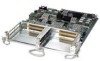
6 C H A P T E R Installing and Removing a Shared Port Adapter This chapter describes how to install or remove SPAs on the Cisco 7600 series routers. This chapter contains the following sections: • Handling SPAs, page 6-1 • SPA Installation and Removal, page 6-2 • Online Insertion and Removal, page 6-3 • Optical Device Maintenance, page 6-3 • Checking the Installation, page 6-4 • SPA Blank Filler Plates, page 6-6 • SPA Cable-Management Brackets, page 6-7 Handling SPAs Each SPA circuit board is mounted to a metal carrier and is sensitive to electrostatic discharge (ESD) damage. Before you begin installation, read the "Preparing to Install a SIP or a Shared Port Adapter," chapter for a list of parts and tools required for installation. Caution Always handle the SPA by the carrier edges and handle; never touch the SPA components or connector pins. (See Figure 6-1.) When a subslot is not in use, a SPA blank filler plate must fill the empty subslot to allow the router or switch to conform to electromagnetic interference (EMI) emissions requirements and to allow proper airflow across the installed modules. If you plan to install a SPA in a subslot that is not in use, you must first remove the SPA blank filler plate. OL-5052-14 Cisco 7600 Series Router SIP, SSC, and SPA Hardware Installation Guide 6-1
-
 1
1 -
2
-
3
-
4
-
5
-
6
-
7
-
8
-
9
-
10
-
11
-
12
-
13
-
14
-
15
-
16
-
17
-
18
-
19
-
20
-
21
-
22
-
23
-
24
-
25
-
26
-
27
-
28
-
29
-
30
-
31
-
32
-
33
-
34
-
35
-
36
-
37
-
38
-
39
-
40
-
41
-
42
-
43
-
44
-
45
-
46
-
47
-
48
-
49
-
50
-
51
-
52
-
53
-
54
-
55
-
56
-
57
-
58
-
59
-
60
-
61
-
62
-
63
-
64
-
65
-
66
-
67
-
68
-
69
-
70
-
71
-
72
-
73
-
74
-
75
-
76
-
77
-
78
-
79
-
80
-
81
-
82
-
83
-
84
-
85
-
86
-
87
-
88
-
89
-
90
-
91
-
92
-
93
-
94
-
95
-
96
-
97
-
98
-
99
-
100
-
101
-
102
-
103
-
104
-
105
-
106
-
107
-
108
-
109
-
110
-
111
-
112
-
113
-
114
-
115
-
116
-
117
-
118
-
119
-
120
-
121
-
122
-
123
-
124
-
125
-
126
-
127
-
128
-
129
-
130
-
131
-
132
-
133
-
134
-
135
-
136
-
137
-
138
-
139
-
140
-
141
-
142
-
143
-
 144
144 -
 145
145 -
 146
146 -
 147
147 -
 148
148 -
 149
149 -
 150
150 -
 151
151 -
 152
152 -
 153
153 -
 154
154 -
155
-
156
-
157
-
158
-
159
-
160
-
161
-
162
-
163
-
164
-
165
-
166
-
167
-
168
-
169
-
170
-
171
-
172
 |
 |
