Cisco 7600 SIP 200 Hardware Installation Guide - Page 155
SPA Cable-Management Brackets
 |
UPC - 746320961286
View all Cisco 7600 SIP 200 manuals
Add to My Manuals
Save this manual to your list of manuals |
Page 155 highlights
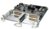
Chapter 6 Installing and Removing a Shared Port Adapter SPA Cable-Management Brackets SPA Cable-Management Brackets SPAs are shipped with an accessory kit that includes cable-management brackets. Figure 6-3 shows cable-management brackets installed in a SPA, as well as cable routing. Figure 6-3 SPA Cable-Management Brackets FAN STATUS 1 WS-X6K-SUP2-2GE STATUS SYSTEMCONSOLPEWR MGRMETSET SUPERVISOR2 CONSOLE CONSOLE PORT MODE PCMCIA EJECT OSM-4OC12 POS-SI 1 3 2 STATUS 2 4 4 PORT OC-12 POS SM IR LINK 1 2 LINK LINK 3 4 LINK 7600-MSC-600 0 3 STATUS MODULAR SERVICES CARD 2 C/A 0 A/L C/A 0 A/L C/A 0 A/L C/A 0 A/L RESET ACTIVE TX RX CARRAILEARRM RX TX PORT 1 ACTIVE TX RX CARRAILEARRM RX TX PORT 2 STATUS SPA-4XOC3-ATM Switch 100% Load PORT 1 1% ACTIVE TX RX CARRAILEARRM RX TX PORT 3 LINK ACTIVE TX RX CARRAILEARRM PORT 2 LINK RX TX PORT4 STATUS 1 3 129582 To install cable-management brackets on a SPA, perform the following steps: Step 1 Step 2 Step 3 Screw the two pull assemblies into both sides of the SPA. Insert the cable-management clip into the slot. To remove the cable-management clip, depress the button on the clip and pull it out. Note Blank filler plugs are provided if no cable-management clips are installed. OL-5052-14 Cisco 7600 Series Router SIP, SSC, and SPA Hardware Installation Guide 6-7
-
 1
1 -
2
-
3
-
4
-
5
-
6
-
7
-
8
-
9
-
10
-
11
-
12
-
13
-
14
-
15
-
16
-
17
-
18
-
19
-
20
-
21
-
22
-
23
-
24
-
25
-
26
-
27
-
28
-
29
-
30
-
31
-
32
-
33
-
34
-
35
-
36
-
37
-
38
-
39
-
40
-
41
-
42
-
43
-
44
-
45
-
46
-
47
-
48
-
49
-
50
-
51
-
52
-
53
-
54
-
55
-
56
-
57
-
58
-
59
-
60
-
61
-
62
-
63
-
64
-
65
-
66
-
67
-
68
-
69
-
70
-
71
-
72
-
73
-
74
-
75
-
76
-
77
-
78
-
79
-
80
-
81
-
82
-
83
-
84
-
85
-
86
-
87
-
88
-
89
-
90
-
91
-
92
-
93
-
94
-
95
-
96
-
97
-
98
-
99
-
100
-
101
-
102
-
103
-
104
-
105
-
106
-
107
-
108
-
109
-
110
-
111
-
112
-
113
-
114
-
115
-
116
-
117
-
118
-
119
-
120
-
121
-
122
-
123
-
124
-
125
-
126
-
127
-
128
-
129
-
130
-
131
-
132
-
133
-
134
-
135
-
136
-
137
-
138
-
139
-
140
-
141
-
142
-
143
-
144
-
145
-
146
-
147
-
148
-
149
-
 150
150 -
 151
151 -
 152
152 -
 153
153 -
 154
154 -
 155
155 -
 156
156 -
 157
157 -
 158
158 -
 159
159 -
 160
160 -
161
-
162
-
163
-
164
-
165
-
166
-
167
-
168
-
169
-
170
-
171
-
172
 |
 |
