Cisco 7600 SIP 200 Hardware Installation Guide - Page 36
Specifying the SIP or SSC Subslot Location for a SPA, show module, sip-disk, show idprom module
 |
UPC - 746320961286
View all Cisco 7600 SIP 200 manuals
Add to My Manuals
Save this manual to your list of manuals |
Page 36 highlights
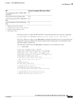
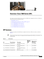
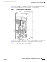
Identifying Slots and Subslots for SIPs and SPAs Chapter 2 Overview: Cisco 7600 Series SIPs 5 1 3 WS-X6K-SUP2-2GE 1 STATUS SYSTEMCONSOLPEWR MGRMETSET CONSOLE PORT MODE SUPERVISOR2 CONSOLE WS-X6K-SUP2-2GE 2 STATUS SYSTEMCONSOLPEWR MGRMETSET CONSOLE PORT MODE SUPERVISOR2 CONSOLE STATUS LINK WS-X6408 1 2 3 8 PORT GIGABIT ETHERNET STATUS LINK WS-X6408 4 1 2 8 PORT GIGABIT ETHERNET WS-X6408 1 2 5 8 PORT GIGABIT ETHERNET LINK LINK PCMCIA EJECT PCMCIA EJECT 3 4 Switch Load 100% 1% Switch Load 100% 1% PORT 1 LINK PORT 1 LINK 5 6 7 PORT 2 LINK PORT 2 LINK 8 LINK LINK LINK LINK LINK 3 4 5 6 7 8 LINK LINK LINK LINK LINK 3 4 5 6 7 8 LINK LINK STATUS LINK LINK LINK LINK LINK LINK LINK LINK 6 7 8 FAN STATUS 9 7600-SIP-200 0 C/A A/L 0 TX RX C/A A/L 1 TX RX C/A A/L 2 TX RX C/A A/L TX 3 STATUS RSXPA-4XT3/E3 1 STATUS SPA INTERFACE PROCESSOR 2 WS-X6224 3 STATUS 24 PORT 100FX WS-X6224 1 LINK 2 LINK 3 LINK 4 LINK 5 LINK 6 LINK 7 LINK 8 LINK 9 10 11 12 13 14 15 16 17 18 19 20 21 22 23 24 LINK LINK LINK LINK LINK LINK LINK LINK LINK LINK LINK LINK LINK LINK LINK LINK STATUS 24 PORT 100FX WS-X6224 1 LINK 2 LINK 3 LINK 4 LINK 5 LINK 6 LINK 7 LINK 8 LINK 9 LINK 10 LINK 11 LINK 12 LINK 13 LINK 14 LINK 15 LINK 16 LINK 17 LINK 18 LINK 19 LINK 20 LINK 21 LINK 22 LINK 23 LINK 24 LINK STATUS 24 PORT 100FX 1 LINK 2 LINK 3 LINK 4 LINK 5 LINK 6 LINK 7 LINK 8 LINK 9 LINK 10 LINK 11 LINK 12 LINK 13 LINK 14 LINK 15 LINK 16 LINK 17 LINK 18 LINK 19 LINK 20 LINK 21 LINK 22 LINK 23 LINK 24 LINK o o INPUT OK FAN OUTPUT OK FAIL INPUT OK FAN OUTPUT OK FAIL 2 4 138980 1 SIP subslot 0 2 SIP subslot 1 3 SIP subslot 2 4 SIP subslot 3 5 Chassis slots 1-9 (numbered from right to left) (numbered from top to bottom) Some commands allow you to display information about the SIP itself, such as show module, show sip-disk, show idprom module, show hw-module slot, and show diagbus. These commands require you to specify the chassis slot location where the SIP that you want information about is installed. For example, to display status and information about the SIP installed in slot 6 as shown in Figure 2-1, enter the following command: Router# show module 6 For more information about SIP commands, refer to the Cisco IOS Software Releases 12.2SR Command References and to the Cisco IOS Software Releases 12.2SX Command References. Specifying the SIP or SSC Subslot Location for a SPA SIP subslots begin their numbering with "0" and have a horizontal or vertical orientation depending on the orientation of the SIP in the router chassis slot, as shown in the "SIP, SSC, and SPA Product Overview" chapter of the Cisco 7600 Series Router SIP, SSC, and SPA Software Configuration Guide. Cisco 7600 Series Router SIP, SSC, and SPA Hardware Installation Guide 2-4 OL-5052-14
-
 1
1 -
2
-
3
-
4
-
5
-
6
-
7
-
8
-
9
-
10
-
11
-
12
-
13
-
14
-
15
-
16
-
17
-
18
-
19
-
20
-
21
-
22
-
23
-
24
-
25
-
26
-
27
-
28
-
29
-
30
-
 31
31 -
 32
32 -
 33
33 -
 34
34 -
 35
35 -
 36
36 -
 37
37 -
 38
38 -
 39
39 -
 40
40 -
 41
41 -
42
-
43
-
44
-
45
-
46
-
47
-
48
-
49
-
50
-
51
-
52
-
53
-
54
-
55
-
56
-
57
-
58
-
59
-
60
-
61
-
62
-
63
-
64
-
65
-
66
-
67
-
68
-
69
-
70
-
71
-
72
-
73
-
74
-
75
-
76
-
77
-
78
-
79
-
80
-
81
-
82
-
83
-
84
-
85
-
86
-
87
-
88
-
89
-
90
-
91
-
92
-
93
-
94
-
95
-
96
-
97
-
98
-
99
-
100
-
101
-
102
-
103
-
104
-
105
-
106
-
107
-
108
-
109
-
110
-
111
-
112
-
113
-
114
-
115
-
116
-
117
-
118
-
119
-
120
-
121
-
122
-
123
-
124
-
125
-
126
-
127
-
128
-
129
-
130
-
131
-
132
-
133
-
134
-
135
-
136
-
137
-
138
-
139
-
140
-
141
-
142
-
143
-
144
-
145
-
146
-
147
-
148
-
149
-
150
-
151
-
152
-
153
-
154
-
155
-
156
-
157
-
158
-
159
-
160
-
161
-
162
-
163
-
164
-
165
-
166
-
167
-
168
-
169
-
170
-
171
-
172
 |
 |
