Cisco 7600 SIP 200 Hardware Installation Guide - Page 120
-Port Channelized T1/E1 ATM CEoP SPA LEDs - hot swap
 |
UPC - 746320961286
View all Cisco 7600 SIP 200 manuals
Add to My Manuals
Save this manual to your list of manuals |
Page 120 highlights
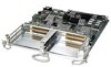
24-Port Channelized T1/E1 ATM CEoP SPA Overview Chapter 3 Overview: Cisco 7600 Series Router Shared Port Adapters • 24-Port Channelized T1/E1 ATM CEoP SPA Patch Panel 24-Port Channelized T1/E1 ATM CEoP SPA LEDs The 24-Port Channelized T1/E1 ATM CEoP SPA has two types of LEDS, as shown in this figure: Figure 3-54 24-Port Channelized T1/E1 ATM CEoP SPA Faceplate WrbseyemhsdetoeonvmnahelosaihtnnCusduwtAdnarUodepwTeppnIrliaOntcwwgNeioltmlhmoiescnincftauumntre.utsrsaotyr, 4 1 A/C (Alarm/Carrier) LED 2 STATUS LED The 24-Port Channelized T1/E1 ATM CEoP SPA LEDs are described in the following table. Table 3-45 24-Port Channelized T1/E1 ATM CEoP SPA LEDs LED Label STATUS A/C Color Off Amber Green Off Green Amber State Off On On Off On On Meaning SPA power is off. SPA power is on and good, and SPA is being configured. SPA is ready and operational. Port is not enabled by software. Port is enabled by software. Port is enabled by software, and there is at least one alarm. 24-Port Channelized T1/E1 ATM CEoP SPA Interface Specifications The physical layer interface for the 24-Port Channelized T1/E1 ATM CEoP SPA is a customer-installed high-density connector. The high-density connector has thumbscrews which should be screwed into the SPA when the cable is installed. 24-Port Channelized T1/E1 ATM CEoP SPA Cables and Connectors The 24-Port Channelized T1/E1 ATM CEoP SPA requires a Cisco cable (part number CABLE-24T1E1J1), which is shown in the following figure. 3-74 Cisco 7600 Series Router SIP, SSC, and SPA Hardware Installation Guide OL-5052-14
-
 1
1 -
2
-
3
-
4
-
5
-
6
-
7
-
8
-
9
-
10
-
11
-
12
-
13
-
14
-
15
-
16
-
17
-
18
-
19
-
20
-
21
-
22
-
23
-
24
-
25
-
26
-
27
-
28
-
29
-
30
-
31
-
32
-
33
-
34
-
35
-
36
-
37
-
38
-
39
-
40
-
41
-
42
-
43
-
44
-
45
-
46
-
47
-
48
-
49
-
50
-
51
-
52
-
53
-
54
-
55
-
56
-
57
-
58
-
59
-
60
-
61
-
62
-
63
-
64
-
65
-
66
-
67
-
68
-
69
-
70
-
71
-
72
-
73
-
74
-
75
-
76
-
77
-
78
-
79
-
80
-
81
-
82
-
83
-
84
-
85
-
86
-
87
-
88
-
89
-
90
-
91
-
92
-
93
-
94
-
95
-
96
-
97
-
98
-
99
-
100
-
101
-
102
-
103
-
104
-
105
-
106
-
107
-
108
-
109
-
110
-
111
-
112
-
113
-
114
-
 115
115 -
 116
116 -
 117
117 -
 118
118 -
 119
119 -
 120
120 -
 121
121 -
 122
122 -
 123
123 -
 124
124 -
 125
125 -
126
-
127
-
128
-
129
-
130
-
131
-
132
-
133
-
134
-
135
-
136
-
137
-
138
-
139
-
140
-
141
-
142
-
143
-
144
-
145
-
146
-
147
-
148
-
149
-
150
-
151
-
152
-
153
-
154
-
155
-
156
-
157
-
158
-
159
-
160
-
161
-
162
-
163
-
164
-
165
-
166
-
167
-
168
-
169
-
170
-
171
-
172
 |
 |
