Cisco 7600 SIP 200 Hardware Installation Guide - Page 54
-Port and 4-Port Clear Channel T3/E3 SPA LEDs, 2-Port and 4-Port Clear Channel T3/E3 SPA Interface
 |
UPC - 746320961286
View all Cisco 7600 SIP 200 manuals
Add to My Manuals
Save this manual to your list of manuals |
Page 54 highlights
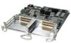
2-Port and 4-Port Clear Channel T3/E3 SPA Overview Chapter 3 Overview: Cisco 7600 Series Router Shared Port Adapters 116851 2-Port and 4-Port Clear Channel T3/E3 SPA LEDs The 2-Port and 4-Port Clear Channel T3/E3 SPA has three types of LEDs: two LEDs for each port on the SPA, and one STATUS LED, as shown in Figure 3-2. Figure 3-2 4-Port Clear Channel T3/E3 SPA Faceplate 2 1 C/A A/L 0 TX RX 34 C/A A/L 1 TX RX C/A A/L 2 TX RX C/A A/L TX 3 STATUS RX SPA-4XT3/E3 5 1 C/A (Carrier/Alarm) LED 2 A/L (Active Loopback) LED 3 TX (Transmit) connector 4 RX (Receive) connector 5 STATUS LED Table 3-4 describes the 2-Port and 4-Port Clear Channel T3/E3 SPA LEDs. Table 3-4 2-Port and 4-Port Clear Channel T3/E3 SPA LEDs LED Label C/A A/L STATUS Color Off Green State Off On Amber On Off Off Green On Amber On Off Off Green On Amber On Meaning Port is not enabled by software. Port is enabled by software, and there is a valid E3 or T3 signal without any alarms. Port is enabled by software, and there is at least one alarm. Port is not enabled by software. Port is enabled by software, and loopback is off. Port is enabled by software, and loopback is on. SPA power is off. SPA is ready and operational. SPA power is on and good, and the SPA is being configured. 2-Port and 4-Port Clear Channel T3/E3 SPA Interface Specifications The framer processes incoming and outgoing T3 (cbit, m13/m23, and unframe) and E3 (g751, g832, and unframe) frames. The framer operates at T3/E3 line rates (44.736 /34.368 Mbps) depending on the mode in which it is configured. Packet data is transported with a user-configurable encapsulation (such as Point-to-Point Protocol [PPP] or High-Level Data Link Control [HDLC]), and is mapped to T3 and E3 frames. The encapsulations add transport overhead to the packet of data frames before transporting, and are stripped when a packet is transported to the far end. Cisco 7600 Series Router SIP, SSC, and SPA Hardware Installation Guide 3-8 OL-5052-14
-
 1
1 -
2
-
3
-
4
-
5
-
6
-
7
-
8
-
9
-
10
-
11
-
12
-
13
-
14
-
15
-
16
-
17
-
18
-
19
-
20
-
21
-
22
-
23
-
24
-
25
-
26
-
27
-
28
-
29
-
30
-
31
-
32
-
33
-
34
-
35
-
36
-
37
-
38
-
39
-
40
-
41
-
42
-
43
-
44
-
45
-
46
-
47
-
48
-
 49
49 -
 50
50 -
 51
51 -
 52
52 -
 53
53 -
 54
54 -
 55
55 -
 56
56 -
 57
57 -
 58
58 -
 59
59 -
60
-
61
-
62
-
63
-
64
-
65
-
66
-
67
-
68
-
69
-
70
-
71
-
72
-
73
-
74
-
75
-
76
-
77
-
78
-
79
-
80
-
81
-
82
-
83
-
84
-
85
-
86
-
87
-
88
-
89
-
90
-
91
-
92
-
93
-
94
-
95
-
96
-
97
-
98
-
99
-
100
-
101
-
102
-
103
-
104
-
105
-
106
-
107
-
108
-
109
-
110
-
111
-
112
-
113
-
114
-
115
-
116
-
117
-
118
-
119
-
120
-
121
-
122
-
123
-
124
-
125
-
126
-
127
-
128
-
129
-
130
-
131
-
132
-
133
-
134
-
135
-
136
-
137
-
138
-
139
-
140
-
141
-
142
-
143
-
144
-
145
-
146
-
147
-
148
-
149
-
150
-
151
-
152
-
153
-
154
-
155
-
156
-
157
-
158
-
159
-
160
-
161
-
162
-
163
-
164
-
165
-
166
-
167
-
168
-
169
-
170
-
171
-
172
 |
 |
