Craftsman 536.270320 Operation Manual - Page 11
To Operate, Ignition, Key Switch - blade replacement
 |
View all Craftsman 536.270320 manuals
Add to My Manuals
Save this manual to your list of manuals |
Page 11 highlights
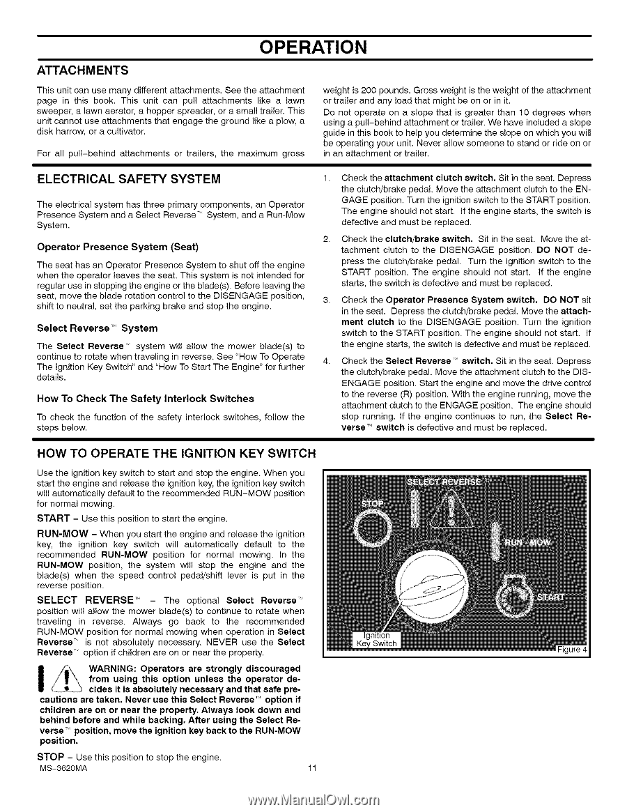
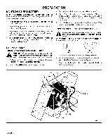
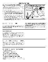
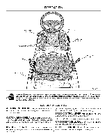
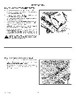
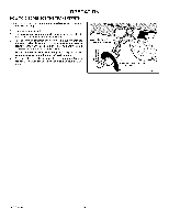
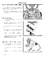
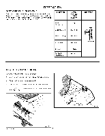
ATTACHMENTS OPERATION This unit can use many different attachments. See the attachment page in this book. This unit can pull attachments like a lawn sweeper, a lawn aerator, a hopper spreader, or a small trailer. This unit cannot use attachments that engage the ground like a plow, a disk harrow, or a cultivator. For all pull-behind attachments or trailers, the maximum gross weight is 200 pounds. Gross weight is the weight of the attachment or trailer and any load that might be on or in it. Do not operate on a slope that is greater than 10 degrees when using a pull-behind attachment or trailer. We have included a slope guide in this book to help you determine the slope on which you will be operating your unit. Never allow someone to stand or ride on or in an attachment or trailer. ELECTRICAL SAFETY SYSTEM The electrical system has three primary components, an Operator Presence System and a Select Reverse T'_System, and a Run-Mow System. Operator Presence System (Seat) The seat has an Operator Presence System to shut off the engine when the operator leaves the seat. This system is not intended for regular use in stopping the engine or the blade(s). Before leaving the seat, move the blade rotation control to the DISENGAGE position, shift to neutral, set the parking brake and stop the engine. Select Reverse'" System The Select Reverse T" system will allow the mower blade(s) to continue to rotate when traveling in reverse. See "How To Operate The Ignition Key Switch" and "How To Start The Engine" for further details. How To Check The Safety Interlock Switches To check the function of the safety interlock switches, follow the steps below. 1. Check the attachment clutch switch, Sit in the seat. Depress the clutch/brake pedal. Move the attachment clutch to the ENGAGE position. Turn the ignition switch to the START position. The engine should not start, if the engine starts, the switch is defective and must be replaced. 2. Check the clutch/brake switch. Sit in the seat. Move the attachment clutch to the DISENGAGE position. DO NOT depress the clutch/brake pedal. Turn the ignition switch to the START position. The engine should not start, if the engine starts, the switch is defective and must be replaced. 3. Check the Operator Presence System switch, DO NOT sit in the seat. Depress the clutch/brake pedal. Move the attachment clutch to the DISENGAGE position. Turn the ignition switch to the START position. The engine should not start, if the engine starts, the switch is defective and must be replaced. 4. Check the Select ReverseT_ switch. Sit in the seat. Depress the clutch/brake pedal. Move the attachment clutch to the DiSENGAGE position. Start the engine and move the drive control to the reverse (R) position. With the engine running, move the attachment clutch to the ENGAGE position. The engine should stop running, if the engine continues to run, the Select Reverse T`_switch is defective and must be replaced. HOW TO OPERATE THE IGNITION KEY SWITCH Use the ignition key switch to start and stop the engine. When you start the engine and release the ignition key, the ignition key switch will automatically default to the recommended RUN-MOW position for normal mowing. START - Use this position to start the engine. RUN-MOW - When you start the engine and release the ignition key, the ignition key switch will automatically default to the recommended RUN-MOW position for normal mowing. In the RUN-MOW position, the system will stop the engine and the blade(s) when the speed control pedal/shift lever is put in the reverse position. SELECT REVERSE "_ - The optional Select Reverse T'_ position will allow the mower blade(s) to continue to rotate when traveling in reverse. Always go back to the recommended RUN-MOW position for normal mowing when operation in Select Reverse __ is not absolutely necessary. NEVER use the Select Reverse__ option if children are on or near the property. _\\\ WfroAmRNuINsGin:g Othpiesraotoprtsion aruenlsetsrsongthlye odpisecroatuorragedde- cides it is absolutely necessary and that safe pre- cautions are taken. Never use this Select Reverse _`_option if children are on or near the property. Always look down and behind before and while backing. After using the Select Re- verse _ position, move the ignition key back to the RUN-MOW position. STOP - Use this position to stop the engine. MS-3620MA 11
-
 1
1 -
2
-
3
-
4
-
5
-
 6
6 -
 7
7 -
 8
8 -
 9
9 -
 10
10 -
 11
11 -
 12
12 -
 13
13 -
 14
14 -
 15
15 -
 16
16 -
17
-
18
-
19
-
20
-
21
-
22
-
23
-
24
-
25
-
26
-
27
-
28
-
29
-
30
-
31
-
32
-
33
-
34
-
35
-
36
-
37
-
38
-
39
-
40
-
41
-
42
-
43
-
44
-
45
-
46
-
47
-
48
-
49
-
50
-
51
-
52
-
53
-
54
-
55
-
56
-
57
-
58
-
59
-
60
-
61
-
62
-
63
-
64
-
65
-
66
-
67
-
68
-
69
-
70
-
71
-
72
-
73
-
74
-
75
-
76
-
77
-
78
-
79
-
80
-
81
-
82
-
83
-
84
-
85
-
86
-
87
-
88
-
89
-
90
-
91
-
92
-
93
-
94
-
95
-
96
-
97
-
98
-
99
-
100
-
101
-
102
-
103
-
104
-
105
-
106
-
107
-
108
 |
 |