Cub Cadet CC30H Riding Lawn Mower Operation Manual - Page 11
Seat Adjustment, Installing The Deck Chute If Equipped, Installing The Mulch Plug If Equipped
 |
View all Cub Cadet CC30H Riding Lawn Mower manuals
Add to My Manuals
Save this manual to your list of manuals |
Page 11 highlights
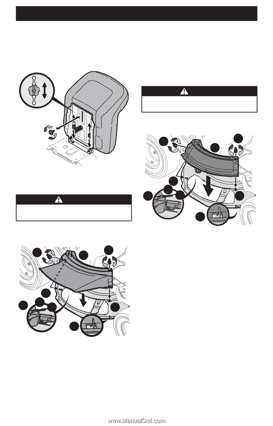
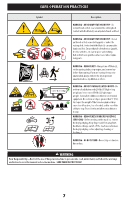
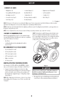
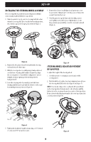
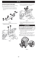
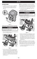
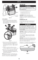
SET-UP SEAT ADJUSTMENT 1. To adjust the position of the seat, remove the adjustment knob on the bottom of the seat. Slide the seat forward or backward as desired. Reinstall the adjustment knob (Figure 10). NOTE: Make certain that the upper-rear portion of deck chute (b) is depressing the safety switch (e) located on the deck surface and under the tab (f) on the rear deck bracket (g). The engine will not start without the deck chute (b) properly in place (Figure 11). 3. Secure the deck chute (b) by tightening the wing knobs (a) removed in Step 1 (Figure 11). INSTALLING THE MULCH PLUG (IF EQUIPPED) WARNING Never operate this riding mower without either the mulch plug or deck chute installed. 1. Remove the wing knobs (a) installed on the mowing deck and retain for later installation (Figure 12). a a b Figure 10 INSTALLING THE DECK CHUTE (IF EQUIPPED) WARNING Never operate this riding mower without either the mulch plug or deck chute installed. 1. Remove the wing knobs (a) installed on the mowing deck and retain for later installation (Figure 11). a a b c e f g c d c f e g c d Figure 12 2. Install the mulch plug (b) into the deck discharge opening on the deck. The rear of the mulch plug (b) should be under the tab (f) on the rear deck bracket (g). The studs (c) on the deck surface will fit through the holes on the upper portion of the mulch plug (b). The small tab (d) on the deck lip area will fit through the square cutout on the lower portion of the mulch plug (b) (Figure 12). NOTE: Make certain that the upper-rear portion of mulch plug (b) is depressing the safety switch (e) located on the deck surface and under the tab (f) on the rear deck bracket (g). The engine will not start without the mulch plug (b) properly in place (Figure 12). 3. Secure the mulch plug (b) by tightening the wing knobs (a) removed in Step 1 (Figure 12). Figure 11 2. Install the deck chute (b) into the deck discharge opening on the deck. The rear of the chute (b) should be under the tab (f) on the rear deck bracket (g). The studs (c) on the deck surface will fit through the holes on the upper portion of the deck chute (b). The small tab (d) on the deck lip area will fit through the square cutout on the lower portion of the deck chute (b) (Figure 11). 11
-
 1
1 -
2
-
3
-
4
-
5
-
 6
6 -
 7
7 -
 8
8 -
 9
9 -
 10
10 -
 11
11 -
 12
12 -
 13
13 -
 14
14 -
 15
15 -
 16
16 -
17
-
18
-
19
-
20
-
21
-
22
-
23
-
24
-
25
-
26
-
27
-
28
-
29
-
30
-
31
-
32
-
33
-
34
-
35
-
36
-
37
-
38
-
39
-
40
-
41
-
42
-
43
-
44
-
45
-
46
-
47
-
48
-
49
-
50
-
51
-
52
-
53
-
54
-
55
-
56
-
57
-
58
-
59
-
60
-
61
-
62
-
63
-
64
-
65
-
66
-
67
-
68
-
69
-
70
-
71
-
72
-
73
-
74
-
75
-
76
-
77
-
78
-
79
-
80
-
81
-
82
-
83
-
84
-
85
-
86
-
87
-
88
-
89
-
90
-
91
-
92
-
93
-
94
-
95
-
96
 |
 |